Below are procedures related to the Crossbars and Friezes functions:
- How to create a Crossbars or friezes function?
- Crossbar or frieze editor;
- How to configure the functions of crossbars or friezes?
- How to define standard assembly of crossbars by registry modules?
- How to associate the crossbars function in the module registry?
- How to enable the Crossbar Editor option on a door?
- How to make crossbars drawings?
- How to redefine variables for crossbars or friezes?
- How to define that a crossbar does not cut the door panel?
- How to identify if the crossbar or friezes inserted in the 3D environment is hidden or apparent?
- How to define the vertical orientation of crossbars or friezes?
- How to define whether the Crossbar Editor will be visible?
- How to change the Crossbar Editor nomenclature?
How to create a Crossbars or friezes function?
To create the crossbars function:
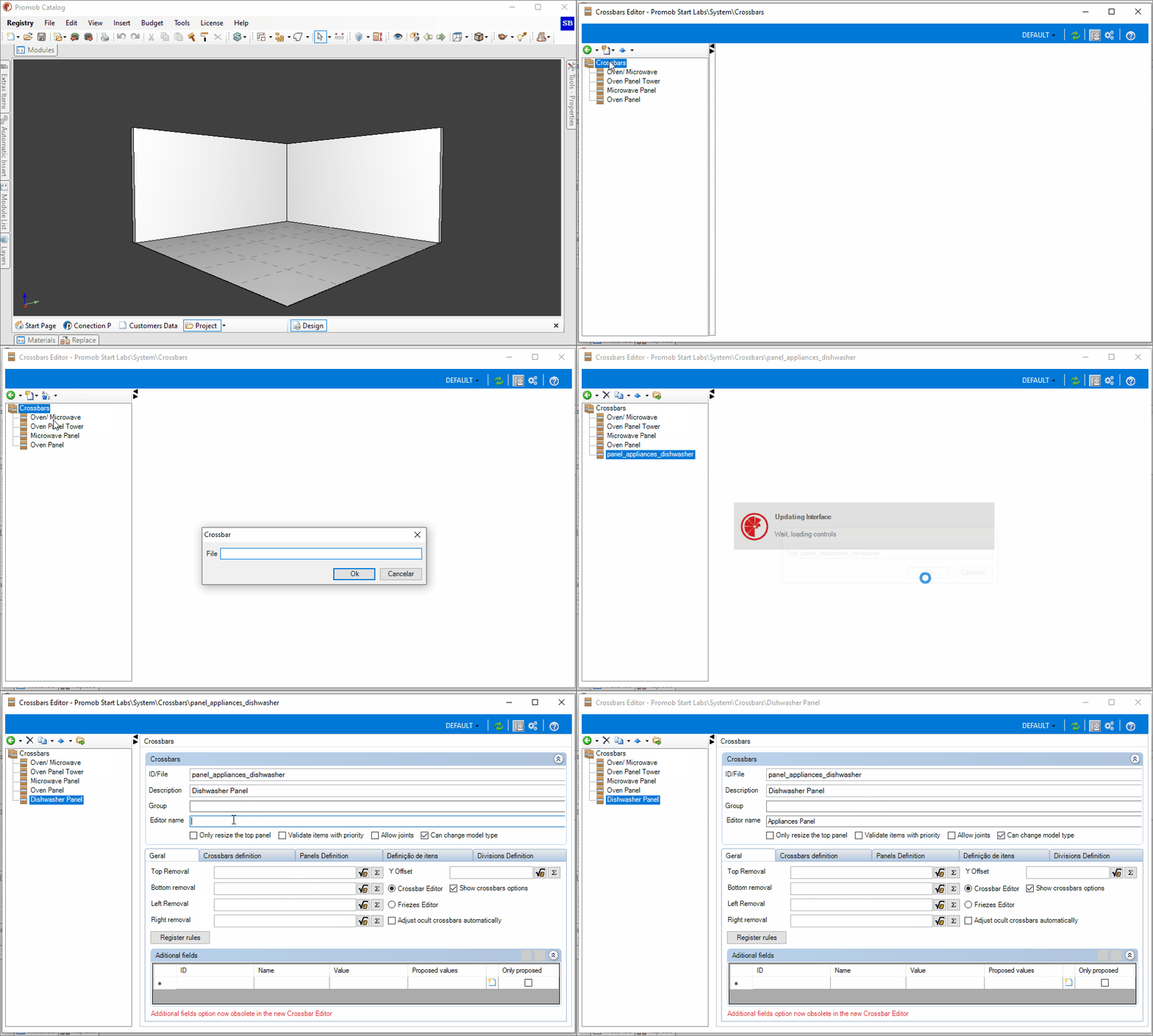
1. Access the Registry - Functions - Crossbars menu.

2. If you already have a crossbars group, click on the group and click New - Crossbars, or select Crossbars Group.

3. Fill in the File field with the desired name, following the pattern of ID registration, without special characters.

4. The registered information will be displayed in the highlighted field. Fill in the Description field as desired.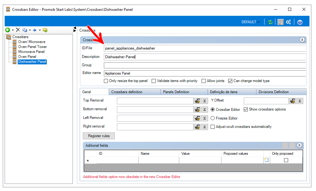
5. Select the crossbar created and make the necessary settings.
To select which editor you want to be used, just select the following field:
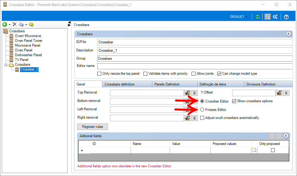
Crossbar or frieze editor
The Crossbar Editor has the function of configuring the crossbars, according to the user's needs.
To access the Editor, proceed as follows:
1. Access the Register - Modules menu.
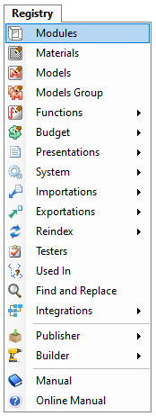
2. Then click on Crossbar Function in the Main menu and select the Edit Function option.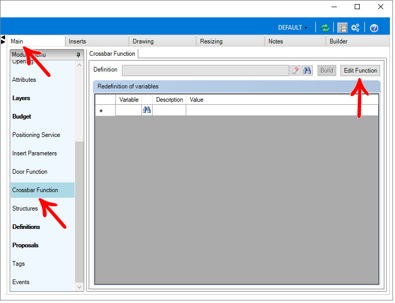
3. Click on the Crossbars definition tab and the following screen opens.
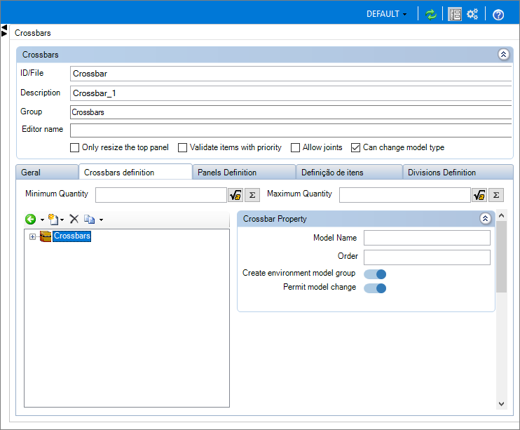

1. Editor Name: This option allows you to name the editor that will appear in the Partner's Promob 3D Environment. If the field is not filled in, it assumes the default value, Edit sleepers;
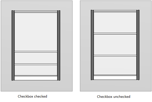
2. Only resize the top panel: this option can be checked if you want that, when resizing the door height, only the top panel will change in size.
2. Validate items with priority: with this option selected, Promob will validate items that have priority, according to the user's needs;
2. Allow Join: Allows the function to join.
2. Can change type model: Allows the models to be changed in the function.
3. Maximum quantity: Sets the maximum number of sleepers;
4. Minimum quantity: Sets the minimum number of sleepers;
How to configure the functions of crossbars or friezes?
Through the registration of crossbars functions it is possible to configure the function so that, when inserting the door in the 3D environment, in the item properties, the option Edit crossbars is displayed.
To configure crossbars functions:
1. After creating the crossbars function access the crossbars Function Editor. Check the option Only resize the top panel if you want that when resizing the door height, only the top panel will change in the dimension.
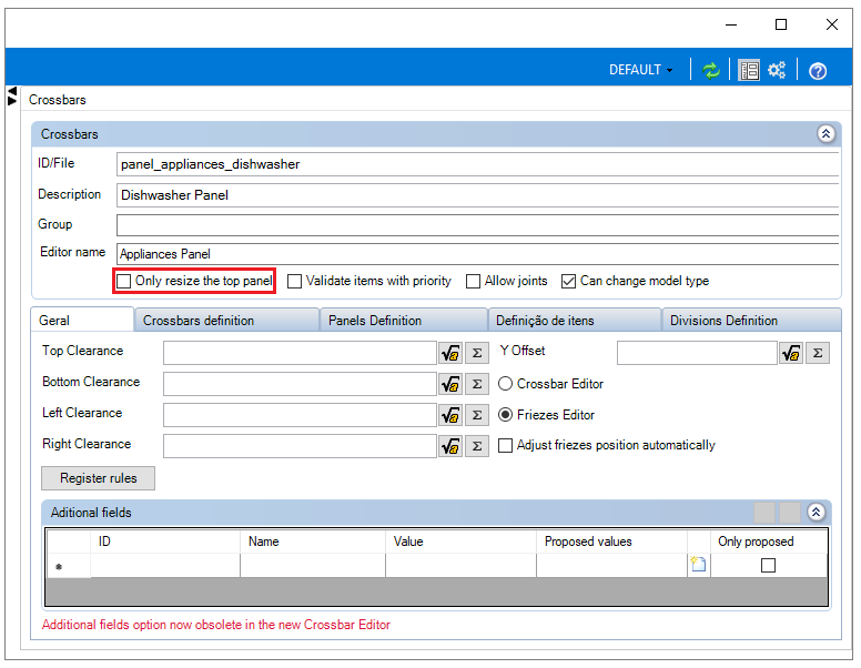
2. On the General tab, configure.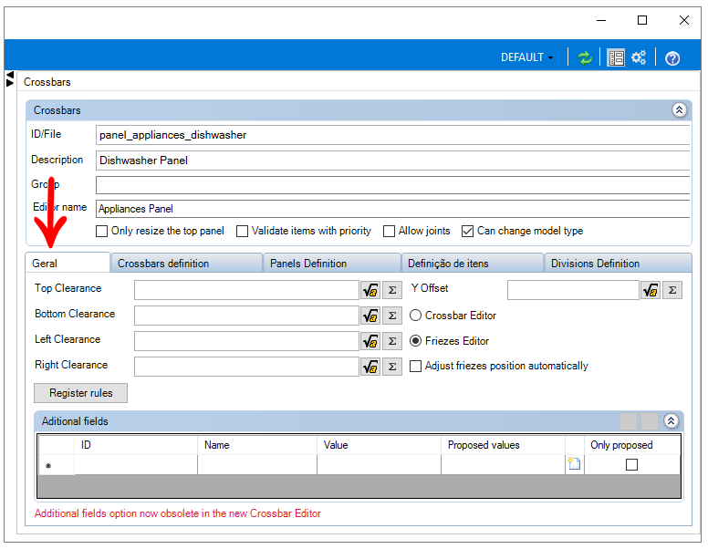
Clearances: in the Upper, Lower, Left, and Right fields, in addition to defining the Clearance in Y.
IMPORTANT: The spacing distances are usually equivalent to the thickness of the upper, lower, left, and right profile so that the panel fits the dimensions of the profiles.
Crossbars Editor or Friezes Editor: check the desired option to select which editor you want to be used.

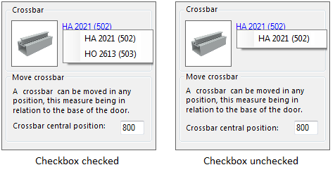
Show crossbars options: when deselecting the option, if the door has crossbars inserted automatically, it will not allow changing crossbars by the Crossbars Editor.
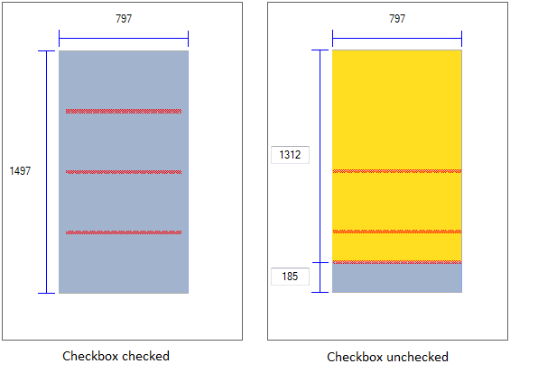
Adjust hidden crossbars automatically: with the option checked, when inserting crossbars hidden by the Crossbars Editor, one by one, they will have their position adjusted automatically with each new insertion, dividing the space of the gaps automatically. In the example below, the crossbars were inserted one by one.
Additional fields: this option is obsolete for the new Crossbar editor. For systems that already used these options, it remains functioning normally in the old editor.
3. Then go to the Crossbars efinition tab and click New. Select one of the options displayed, as desired.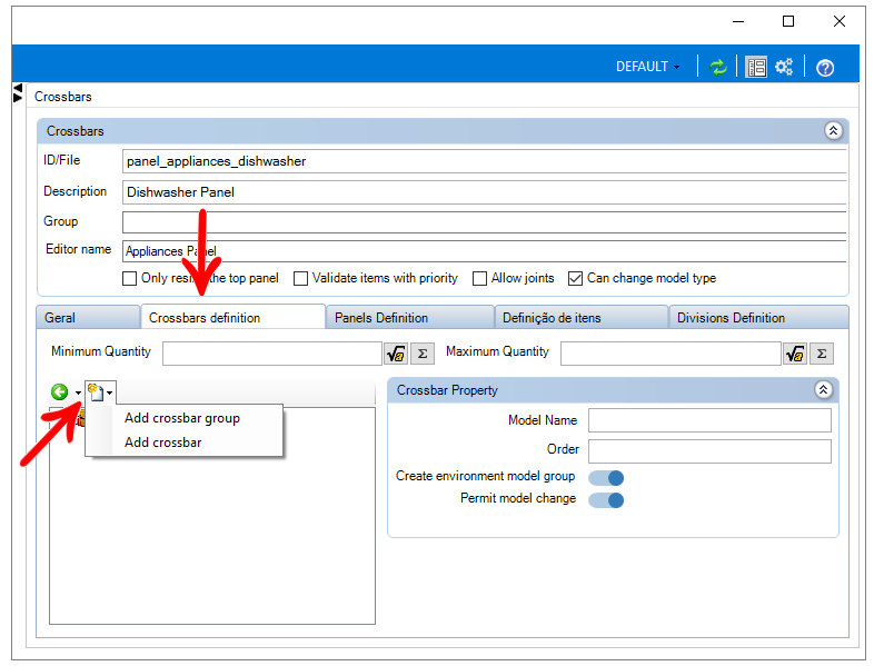
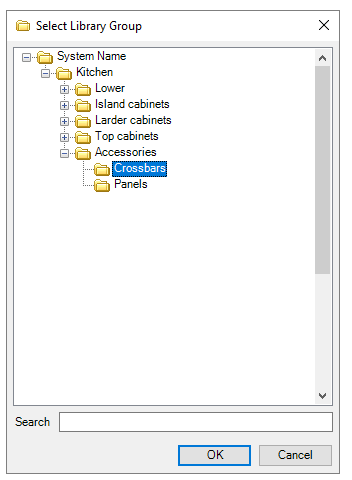
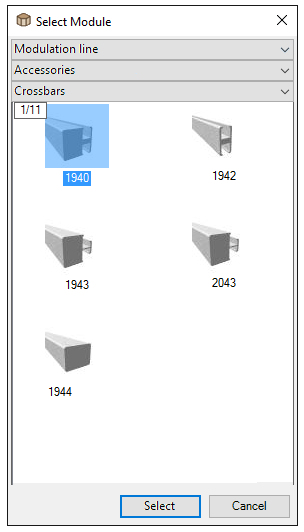
Adding Crossbar Group, when editing crossbars, after insertion, in the environment item, the choice of crossbars from those contained in the group, will be allowed. However, adding Crossbars, the Crossbars Editor will not give you a choice of crossbars.
Add Crossbar Group
Click Find in the window that will appear.

Select the desired crossbar group and click OK.
Add Crossbars
Click Find in the window that will appear

Select the desired crossbar and click Select.
4. By clicking on the added item, some options will be displayed. Make the settings as desired.
When you add a group or a crossbar, the following fields will display:
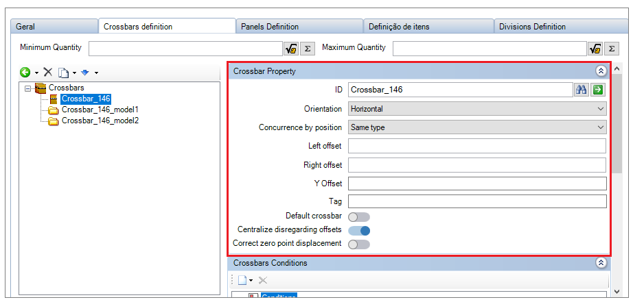
Minimum Quantity: The minimum number of crossbars is configured;
Maximum Quantity: The maximum number of crossbars is configured;
ID: Displays the ID of the selected item (tray or group). You can modify it by clicking on the Find icon;
Orientation: Sets the crosspiece orientation: Horizontal or Vertical;
Concurrence by position: Configures the type of concurrence applied or no concurrence.

Left spacing: Defines the spacing of the crossbar to the left;
Right spacing: Defines the spacing of the crossbar to the right;
Y spacing: Defines the Y spacing of the crossbar;
Tag: Allows that, when changing the model of the crossbar, Promob applies it to all crossings with the same Tag, if the user wishes;
Default crossbar: This allows you to define whether the selected crossbar is the one that will be inserted by default by the editor if automatic insertion is enabled;
Centralize disregarding offsets: It allows defining that the crossbar will enter centered in the panel disregarding the offsets. This option is useful when the clearances are different from each other, and it is necessary to have panels of equal dimensions.
Correct the zero point displacement: This option must be enabled when the crossbar is visible (cuts the panel) and does not have a symmetrical design. Thus, Promob disregards the rule that cuts only half the height of the crossbar and cuts the glass correctly, according to the customer's need;
Crossbar conditions: This allows you to configure visibility conditions for the selected item.
You must define the visibility conditions of the crossbars. Being able to choose between the conditions already available in the Catalog. Defining whether it will be considered a condition X OR a condition Y, but also whether it will be considered a condition X AND a condition Y, if it will be.
To consider the opposite of the condition, click Deny condition.
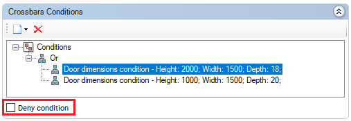
EXAMPLE:
Condition: Consider sleepers over 60cm wide.
Condition denied: Do not consider sleepers over 60cm wide
5. After defining the crossbar, it is necessary to define the panels. Therefore, go to the Panel Definition tab
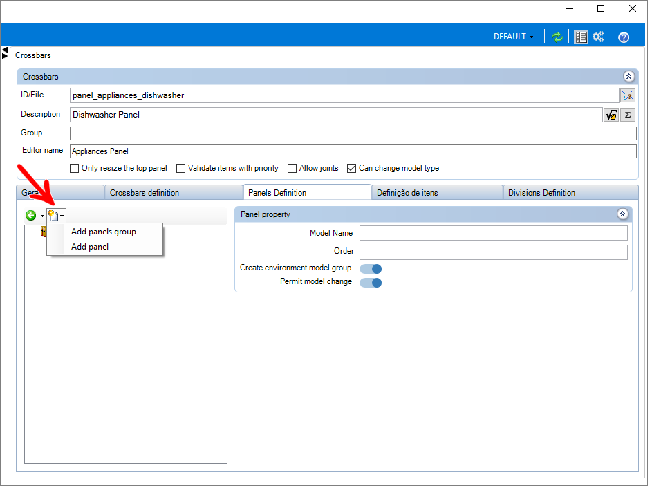
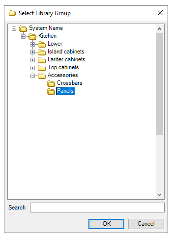
Add panel group
- Click Find in the window that will appear.

- Select the desired panel group and click OK.
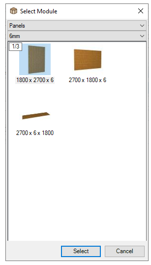
Add panel
- Click Find in the window that will appear

- Select the desired panel and click Select
6. Select the added item so that the editing options are displayed.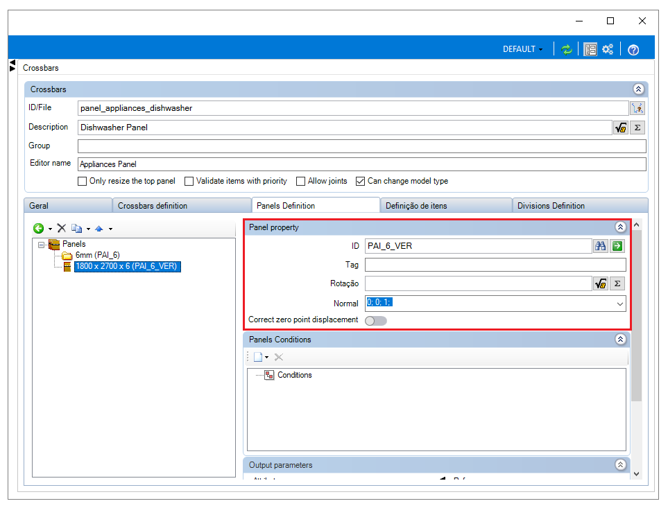
ID: Displays the ID of the selected item (panel or group). You can change it by clicking the Find icon;
Tag: It allows that, when changing the Panel's model, Promob applies it to all panels with the same Tag, if the user wishes;
Rotation: It allows configuring the panel rotation according to the normal.
Normal: Sets the panel's normal.
Correct the zero point displacement: This option must be enabled when the panel is visible (cuts the panel) and does not have a symmetrical design. Thus, Promob disregards the rule that cuts only half the height of the crossbar and cuts the glass correctly, according to the customer's need;
Conditions: It allows configuring visibility conditions for the selected item.
You must define the visibility conditions of the panels. Being able to choose between the conditions already available in the Catalog. Defining whether it will be considered a condition X OR a condition Y, but also whether it will be considered a condition X AND a condition Y if it will be.
To consider the opposite of the condition, click Deny condition.

EXAMPLE:
Condition: Consider sleepers over 60cm wide.
Condition denied: Do not consider sleepers over 60cm wide
IMPORTANT: Only after defining the crossbars and panels settings will it be possible to associate the crossbars function with the door.
7. In the Item Definition tab, it is possible to configure the insertion of items such as TV's in the panels. To add an item, click Add Item.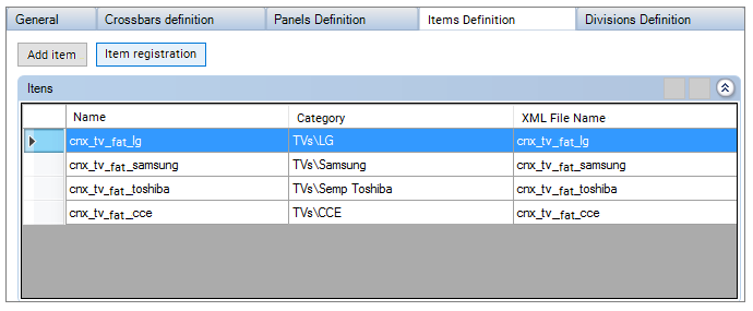
8. After making the desired changes, click the Refresh icon in the header. 
How to redefine variables for crossbars or friezes?
The redefinition of variables can be used when a certain group of doors has the same crossbar function applied, however, a certain door has different clearance settings, thus, this redefinition allows these settings to be edited only for a certain door, avoiding the need to register new crossbars function, just for this situation.
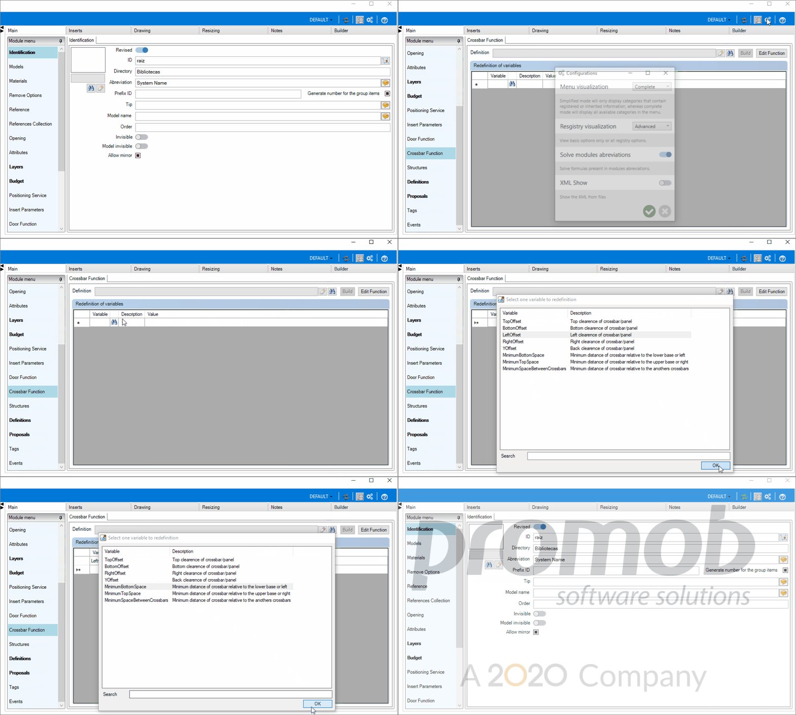
To apply redefinition of crossbars variables:
1. Access the Register - Modules menu.
2. Select the door whose settings will be reset by the Navigation Tree;
3. In the Main tab, with the Advanced mode, access Crossbar Function.
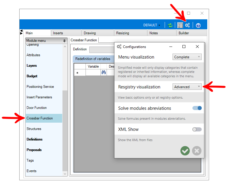
4. After associating the crossbars function, under Reset Variables click Find.
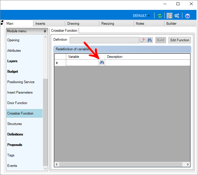
5. Select the variable you want to redefine.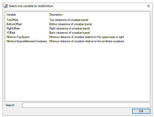
6. Reset the Value field as desired.
7. After making changes, click the Refresh icon in the header. 
How to identify if the crossbar or friezes inserted in the 3D environment is hidden or apparent?
To identify whether the crossbar inserted in the 3D environment is hidden or visible, it is possible to use the ISHIDDENCROSSBAR attribute, which stores the information that determines whether the crossbar is hidden or not:
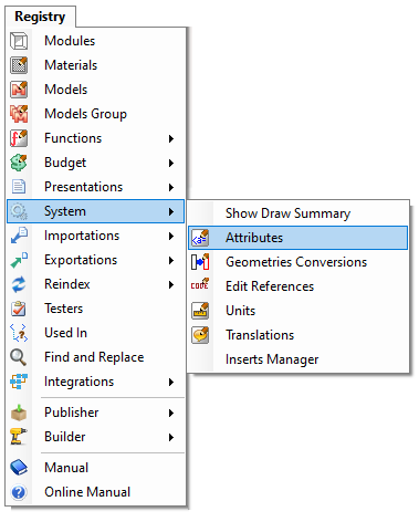
1. In the Catalog, access the Register - System - Attributes menu and create the attribute, defining:
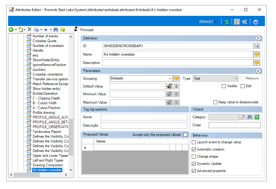
ID: ISHIDDENCROSSBAR
Name: It's a hidden crossbar.
Description: Stores the information that determines whether the crossbar is hidden or not.
Category: Entity
Type: True / False
Default value: False
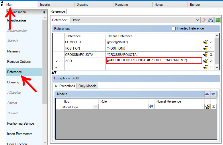
2. To test the attribute, select the crossbar to which you want to apply the configuration via the Module Editor. In the Main - References tab:
- Insert a new line "ADD" with the content @(#ISHIDDENCROSSBAR# ? 'HIDE' : 'APPARENT')
- Change the content of the "COMPLETE" line by adding "$ADD$"
3. Update the registration to apply the changes.
4. Insert a system door in the 3D environment. Right-click on the door and select the option Edit crossbars. Insert the crossbar that had the attribute registered.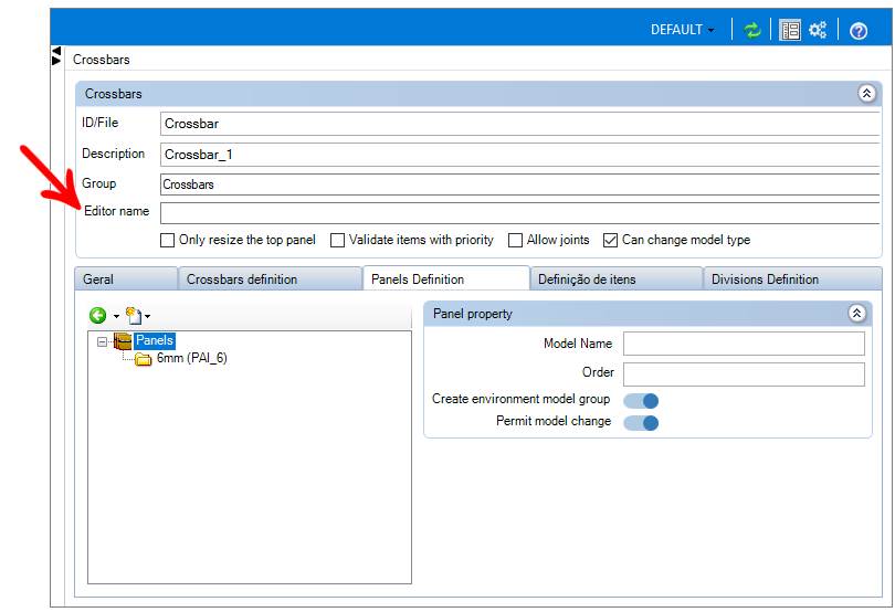
5. Select the crossbar by double-clicking the mouse and consult the Promob status bar to check whether the crossbar is hidden or visible.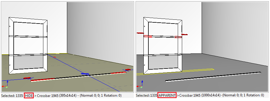
How to define vertical orientation of a crossbars or friezes?
To set the vertical orientation of a crossbar:
1. Access the Registry - Functions - Crossbar menu.
2. Select the lane to which you want to apply the settings via the Navigation Tree.
3. Access the Crossbar Definition tab and select the desired crossbar or group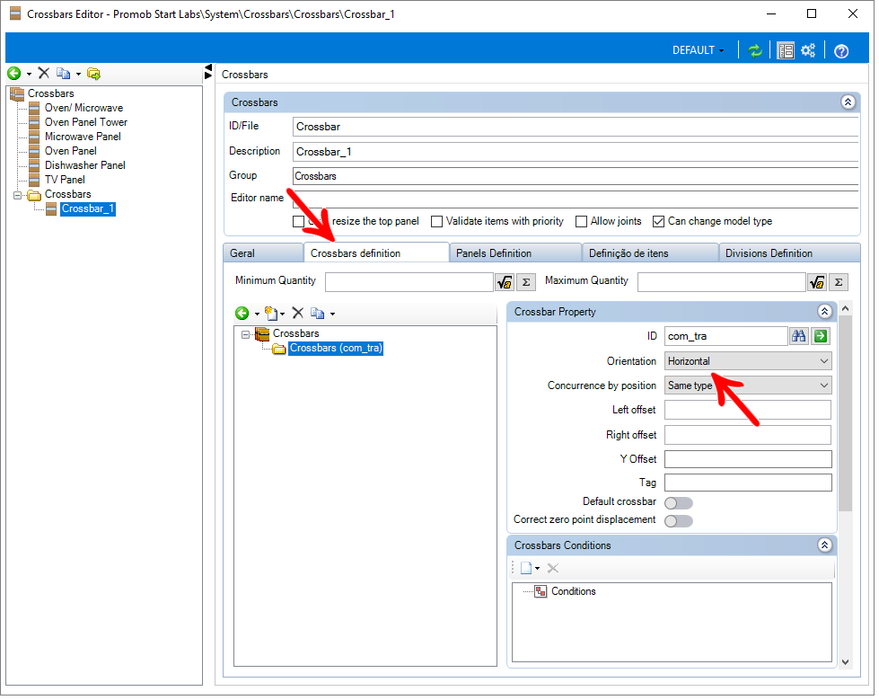
4. In Orientation, select the Vertical option.
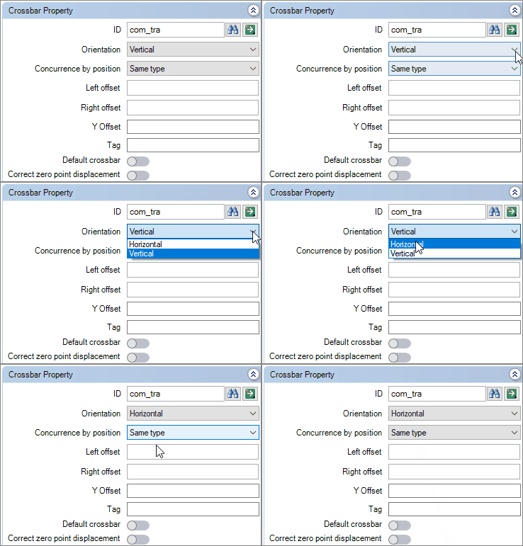
5. After the changes, click Refresher in the header. 
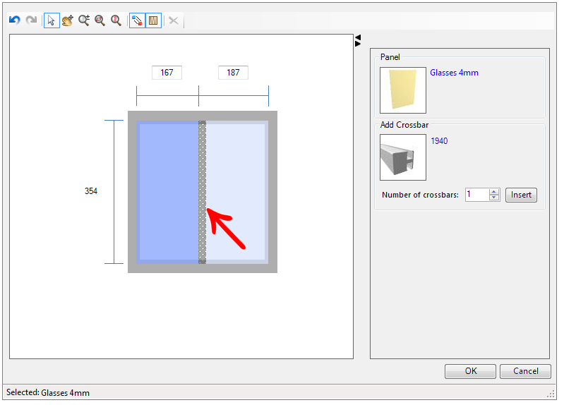
6. In the Crossbar Editor, the crossbar will be inserted vertically, as shown below.
How to define whether the Crossbar Editor will be visible?
Using the CanEditCrossbar attribute, we define the visibility of the Crossbar Editor in the 3D environment. In it, we use N to say that the Editor will not be available and Y for that it will be. In addition to reporting visibility, we can define a condition for this visibility. For this:
1. Register the attribute on the entities tab, as shown in the image: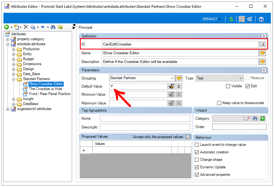
2. Access the Module register, in the Attributes tab and enter its value (N or Y). If there is a visibility condition, such as the following example, which defines that the Crossbar Editor will not be visible if the width is less than 300. Otherwise, it will be visible.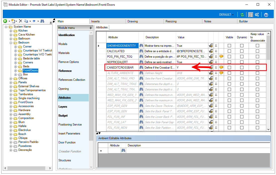
How to change the Crossbar Editor nomenclature?
To change the name of the Crossbar Editor:
1. Access the Register - Functions - Crossbars menu.
2. The following screen opens: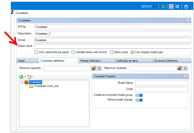
3. The Editor Name option allows you to name the editor that will appear in the Promob 3D Environment, as needed by the user.
EXAMPLE: Electro Panel.