Modules that allow dimension changes often need to follow certain rules so that their resizing is simulated correctly. By default, the modules respect the general resizing standard, where the module is scaled.
Below are procedures on Resizing:
- How to set default resizing?
- How to customize the resizing?
- How to set a visible resizing attribute in properties?
Resizing specifications:
- Parametric A
- Parametric AB
- Parametric ADir
- Parametric in the Middle
- Parametric Cut to Height
- Parametric Cut to Width
- Parametric Cut to Depth
- Parametric Cut in Width and Height
- Parametric by the Sides Conserving a Space in the Center
- Parametric by the Sides Conserving a Space in the Center and at the Edges
- Parametric by the Sides Conserving a Space in the Center and at the Edges in Width and Height
- Parametric Corner 90 AB
- Parametric Top L AB
- Parametric Diagonals
- Parametric E
- Parametric IJ
- Parametric IJDir
- Parametric Height in the Middle
- Parametric Medium Using Limit
How to set predefined resizing?
Resizing can be defined in groups, being respected by all items belonging to the group. An item belonging to a group that has resizing applied can be redefined.
To set a default resize:
1. Access the Register - Modules menu.
2. Select the module / group that must be resized in the Navigation Tree.
3. Access the Resizing tab.

4. Check the Predefined resizing option.
5. Click the Find icon next to the Resizing field.
6. Find and select the resize to be used as needed, and click OK.
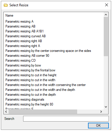
7. After the changes, click the Refresh icon in the header.
How to customize the resize?
The resizes created can only be defined for modules with a single design register. Through the Resizing tab, located next to the Navigation Tabs, it is possible to create rules for resizing.
To create a Resize:
1. Access the Register - Modules menu.
2. Select the module that must be resized in the Navigation Tree.
3. Access the Resizing tab.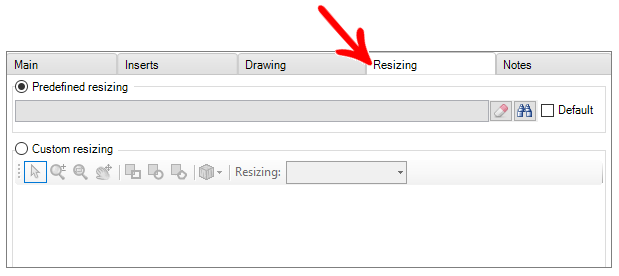
4. Check the option Custom resizing.
5. Customize the resize: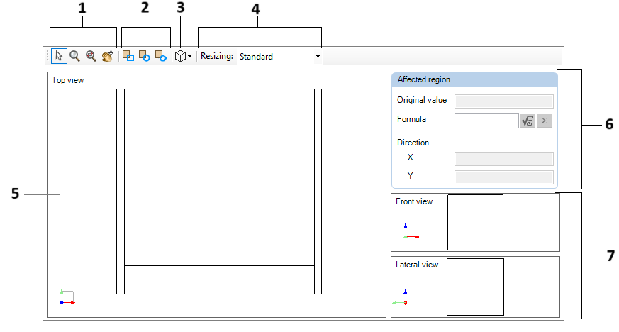
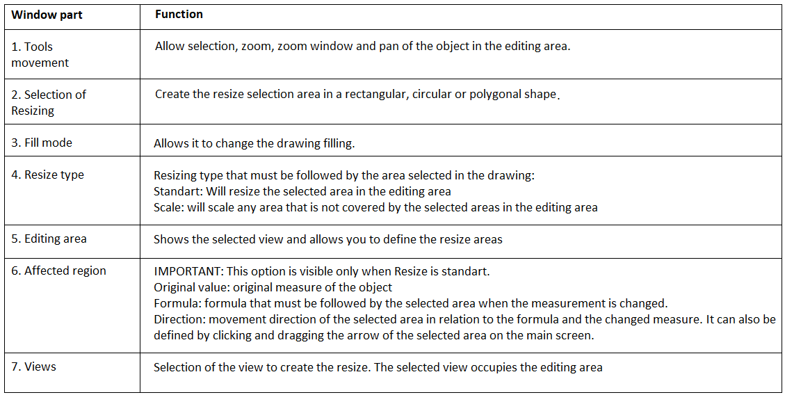
Standard Resizing
To create Standard resizing:
In the module register, on the Resizing tab, on Resizing choose the Standard option;

Choose the form of resizing to be created in the resize selection tool;

Click on the Edit Area at the start point of the area to be resized, drag the mouse defining the shape, and then click on the end point of the area to be resized;
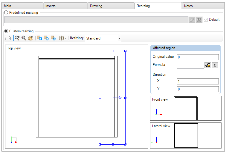
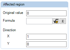
In the affected region, set the Original Value, Formula and Direction for the selection created;
Scalar Resize
When resizing is the Scalar type, the field for defining the type of increment and orientation to be followed is added.

To create Scalar resize:
In the module register, in the Resizing tab, in Resizing choose the Scalar option;

Choose the form of resizing to be created in the resize selection tool;

Click in the Editing Area at the start point of the area to be resized, drag the mouse defining the shape and then click on the end point of the area to be resized;
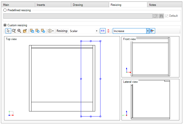
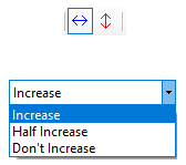
Define the direction of movement and the type of Increment to be followed;
6. After making changes, click Refresh in the header.
Parametric A
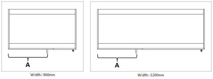
This resizing is used so that the module can have its dimensions changed without any part of the module drawing on the left not being deformed.
The principle of this resizing is to change the width dimensions, keeping a fixed measure stipulated on the left.
Application example: Straight Left Corner.
To apply the resize:
1. Set the resize.
2. Select Parametric A resizing and click OK.
3. The message below will appear. Click Yes to add the attribute.

4. Then click Yes, go to the Main tab and click the Attributes tab and set the value of attribute A.
A: measure to be conserved in width.
5. Click the Refresh icon to apply the changes.
Below is an example of the application of Parametric A resizing:
It is possible to notice that the width has been changed, however the measurement in A, on the left, has remained the same.
Parametric AB
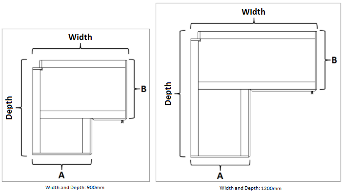
This resizing is used so that the module can have its dimensions changed without leaving a part of the module's design on the left in the Width and Depth of the background forward without suffering deformations.
The principle of this resizing is to change the dimensions in width and depth, keeping a fixed measure stipulated in width and another in depth.
Application example: Corner L
To apply the resize:
1. Set the default resize.
2. Select Parametric AB resizing and click OK.
3. The message below will appear. Click Yes to register the attribute value.

4. After clicking Yes, go to the Main tab and click the Attributes tab, and set attributes A and B.
A: measure to be conserved in width.
B: measure to be conserved in depth. 
5. Click the Refresh icon to apply the changes.
Below is an example of application of Parametric AB resizing:
It is possible to notice that the dimensions in Width and Depth have been changed, while the dimensions in A and B have been maintained.
Parametric ADir
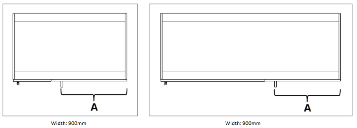
This resizing is used so that the module can have its dimensions changed without any part of the design of the module on the right not being deformed.
The principle of this resizing is to change the width dimensions, keeping a fixed measure stipulated on the right.
Application example: Right Straight Corner.
To apply the resize:
1. Set the resize.
2. Select Parametric ADir resizing and click OK.
3. The message below will appear. Click Yes to register the attribute value:

4. After clicking Yes, go to the Main tab and click the Attributes tab, and set attribute A:
A: measure to be conserved in width.

5. Click the Refresh icon to apply the changes.
Below is an example of the application of the Parametric ADir resizing:
It is possible to notice that the width has been changed, however the measurement in A, on the right, has remained the same.
Parametric in the Middle
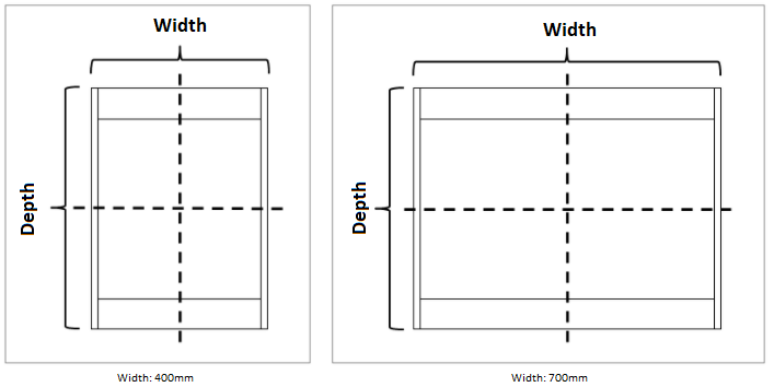
Resizing used so that the module can have its dimensions changed without the ends being deformed
It is the most commonly used resize.
Application example: Cabinets, Wardrobe, Countertop, Bed, etc
To apply the resize:
1. Set the resize.
2. Select the resizing Parametric in the middle and click OK.
3. Click the Refresh icon to apply the changes.
Below is an example of the application of Parametric resizing in the Middle:
It is possible to notice that the width has been changed, however the ends remain the same because the resizing was done in the middle.
Parametric Cut to Height
This resizing is used so that the module can have its dimension changed without its design changing the shape, that is, when the module size is decreased, it is as if the design was just cut in height, and not “shrunk” .
Application example: Door with negatives.
To apply the resize:
1. Set the resize.
2. Select the resize Parametric to Cut to Height and click OK.
3. Click the Refresh icon to apply the changes.
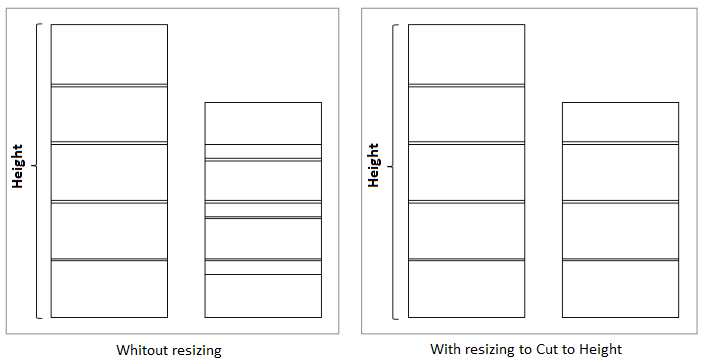
Below is an example of the application of resizing Parametric to Cut to Height:
It is possible to notice in the first image that, without the resizing, after changing the height of the panel, the negatives were resized and became unconfigured. In the image on the right, with the resizing to Cut to Height, the negatives did not have their dimensions changed because the panel was only cut at height.
Parametric Cut to Width
This resizing is used so that the module can have its dimension changed without its design changing the shape, that is, when the module size is decreased, it is as if the design were just cut to width, and not “shrunk”.
Application example: Door with vertical negatives.
To apply the resize:
1. Set the resize.
2. Select resizing Parametric to Crop to Width and click OK.
3. Click the Refresh icon to apply the changes.
Below is an example of the application of Parametric resizing to Cut to Width:
It is possible to notice in the first image that, without resizing, after changing the width of the panel, the negatives were resized and became unconfigured. In the image on the right, with the resizing to Cut to Width, the negatives did not have their dimensions changed, as the panel was only cut to width.

Parametric Cut to Depth
This resizing is used so that the module can have its dimension changed without its design changing the shape, that is, when the module size is decreased, it is as if the design were just cut in depth, and not “shrunk”.
Application example: Objects with details in the horizontal direction.
To apply the resize:
1. Set the resize.
2. Select resizing Parametric to Cut to Depth and click OK.
3. Click the Refresh icon to apply the changes.
Below is an example of the application of Parametric resizing to Cut to Depth:
It is possible to notice in the first image that, without the resizing, after changing the depth of the panel, the negatives were resized and became unconfigured. In the image on the right, with the resizing to Cut to Depth, the negatives did not have their dimensions changed, as the panel was only cut at depth.

Parametric Cut in Width and Height
This resizing is used so that the module can have its dimensions changed without its design changing the shape, that is, when the module size is decreased, it is as if the design were cut in width and height, and not “shrunk”.
Application example: Panels with horizontal and vertical details.
To apply the resize:
1. Set the resize.
2. Select resizing Parametric to Cut in Width and Height and click OK.
3. Click the Refresh icon to apply the changes.
Below is an example of the application of resizing Parametric to Cut in Width and Height:
It is possible to notice in the first image that, without the resizing, after changing the width and height of the panel, the negatives were resized and became unconfigured. In the image on the right, with the resizing to Cut in Width and Height applied to the item, the negatives did not have their dimensions changed, as the panel was only cut in width and height.

Parametric by the Sides Conserving a Space in the Center
This resizing is used so that the module can have its dimensions changed by defining a space in the center of the drawing to not be changed, that is, the module is resized but a certain space in the center does not change.
Application example: Drawers with central parts.
To apply the resize:
1. Set the resize.
2. Select the resizing Parametric by the Sides Conserving a Space in the Center and click OK.
3. The message below will appear. Click Yes to register the attribute value:

4. When you click Yes, the Attributes tab will open automatically, with attributes A, B and C. Define only one of the attributes, as needed, and remove the others:
A: measured at the center to be kept at the center in width.
B: measured at the center to be kept at the center in depth.
C: measure in the center to be kept in the center at the time.
IMPORTANT: This resizing calculates the dimensions of the attributes (A, B and C) starting from the central point of the entity.

5. Click the Refresh icon to apply the changes.
It is possible to notice in the example below that the tandembox drawer has a detail in the center that cannot be resized when the width of the drawer is changed. Resizing was applied with attribute A and the dimension of the configured center part. In this way, in the center, this dimension is maintained when the width is changed.

Parametric by the Sides Conserving Space in the Center and at the Edges
This resizing is used so that the module can have its dimensions changed by defining a space in the center and on the edges of the drawing so as not to change, that is, the module is resized but a certain space in the center and a space on the edges do not change .
Application example: Wire drawers with details on the edges.
To apply the resize:
1. Set the resize.
2. Select the resizing Parametric by the Sides Conserving a Space in the Center and the Borders and click OK.
3. The message below will appear. Click Yes to register the attribute value.

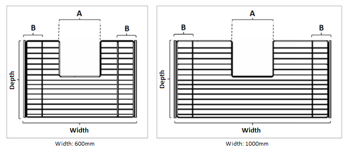
4. When you click Yes, the Attributes tab will open automatically, with attributes A and B. Define both attributes, as needed:
A: measure to the center to be kept in the center (central point).
B: measure to be conserved at the edges (starting from zero point).
5. Click the Refresh icon to apply the changes.
It is possible to notice in the example below that the wire drawer has details in the center and at the edges that cannot be resized when the width of the drawer is changed. Resizing was applied with attribute A with the dimension of the configured central part, and attribute B with the dimension of the edges to be preserved. In this way, at the center and at the edges these dimensions are maintained when the width is changed.
Parametric by the Sides Conserving a Space in the Center and at the Edges in Width and Height
This resizing is used so that the module can have its dimensions changed by defining a space in the center and at the edges, in the width and height of the drawing so as not to change, that is, the module is resized, but a certain space in the center and a space at the edges do not change, either in height or width.
Application example: module with partitions and shelves.
To apply the resize:
1. Set the resize.
2. Select the resizing Parametric by the Sides Conserving a Space in the Center and the Borders in Width and Height and click OK.
3. The message below will appear. Click Yes to register the attribute value:

4. When you click Yes, the Attributes tab will open automatically, with attributes A, B, C and D. Set the values as needed:
A: measured at the center to be kept wide.
B: measured on the sides to be kept wide.
C: measured in the center to be kept at height.
D: measured on the sides to be kept at height.
IMPORTANT: The values shown in the image are the default values of the attributes and do not represent an example.
5. Click the Refresh icon to apply the changes.
You can see in the example below that the module has a shelf and partition, so when resizing the item, these components were not resized. Resizing was applied with attributes A, B, C and D, with the dimensions of the measures to be kept in the center and sides in width, and in the center and sides (bases) in height, respectively. In this way, in the center and at the edges these dimensions are maintained when the dimensions (height and width) are changed.

Parametric Corner 90 AB
This resizing is used so that the module can have its dimensions changed without a part in the center of the module's design being deformed.
Application example: Corner L. shelf.
To apply the resize:
1. Set the resize.
2. Select the resizing Parametric Corner 90 AB and click OK.
3. The message below will appear. Click Yes to register the attribute value:

4. When you click Yes, the Attributes tab will open automatically, with attributes A, B and ABOrig. Set the values as needed:
A: measured at the center to be kept in width.
B: measured on the sides to be kept in width.
ABOrig: measure A and B original of the drawing.
IMPORTANT: The values shown in the image are the default values of the attributes and do not represent an example.
5. Click the Refresh icon to apply the changes.
It is possible to see in the example below that the shelf has an area in the center of the drawing that cannot be changed, so, when increasing the item's dimension, this region has not been changed. Resizing was applied with attributes A, B, and ABOrig, with the dimensions of the measures to be kept in the center and sides in width and the original measure A and B in the drawing. In this way, the region is maintained when the dimensions are changed.
IMPORTANT: The angle and shape of the detail in the center of the drawing is not respected with this resized.

Parametric Top L AB
This resizing is used so that the module can have its dimensions changed without the deformation of the angle in the center of the module drawing.
Application example: L corner top with angle.
IMPORTANT: This resizing only applies when the radius of the angle is less than the remaining measure of A.
To apply the resize:
1. Set the resize.
2. Select the resizing Parametric Table L AB and click OK.
3. The message below will appear. Click Yes to register the attribute value:

4. When you click Yes, the Attributes tab will open automatically, with attributes A, B, ABOrig and LAngulo. Set the values as needed:
A: measured at the center to be kept in width.
B: measured on the sides to be kept in width.
ABOrig: measure A and B original of the drawing (A and B must be the same)
IMPORTANT: It is necessary that the measurements A and B of the original drawing are the same. Resizing will not work correctly if there is a difference between these measurements in the original drawing.
LAngulo: angle radius.
IMPORTANT: The values shown in the image are the default values of the attributes and do not represent an example.
5. Click the Refresh icon to apply the changes.
It is possible to notice in the example below that the table has an angle, therefore, when increasing the dimension of the item, this angle has not been changed. Resizing was applied with the attributes A, B, and ABOrig, with the dimensions of the measures to be preserved and with the original measurement of the drawing of both A and B, in addition to the attribute LAngulo with the radius of the angle. In this way, the angle is maintained when the dimensions are changed.

Parametric Diagonals
The principle of this resizing is to change the dimensions of width and depth, keeping a fixed measure, stipulated on the Right, without changing the diagonal angle.
Application example: Diagonal corner modules.
To apply the resize:
1. Set the resize.
2. Select the Diagonal Parametric resizing and click OK.
3. The message below will appear. Click Yes to register the attribute value:

4. When you click Yes, the Attributes tab will open automatically, with the K and KOrig attribute. Set the values as needed:
K: measure to be conserved in depth.
KOrig: original K measure of the drawing.
IMPORTANT: The values shown in the image are the default values of the attributes and do not represent an example.
5. Click the Refresh icon to apply the changes.
Below is an example of applying Diagonal Parametric resizing:
It is possible to notice that, after changing the width and depth of the module, the dimension in K remained the same.

Parametric E
This resizing is used so that the module can have its dimension changed without its design changing the shape, that is, when the measure of the module is changed, the front angle remains coherent.
Application example: Tops with frontal cutout.
To apply the resize:
1. Set the resize.
2. Select Parametric E resizing and click OK.
3. Click the Refresh icon to apply the changes.
Below is an example of the application of Parametric E resizing:
It is possible to notice that, after changing the width and depth of the module, the angle of curvature of the frontal cutout remained the same.

Parametric IJ
The principle of this resizing is to change the dimensions of width and depth, keeping a fixed measure, stipulated to the Right (J) and to the Front (Width - I), without changing the width of the chamfer.
Application example: Chamfered tops with chamfer on the right.
IMPORTANT: This resizing applies to items that must keep a fixed measurement in front and to the right.
To apply the resize:
1. Set the resize.
2. Select IJ Parametric resizing and click OK.
3. The message below will appear. Click Yes to register the attribute value:

4. When you click Yes, the Attributes tab will open automatically, with the attribute I, J, IOrig and JOrig. Set the values as needed:
I: measure subtracted from the total width to obtain the measure to be kept in width.
J: measure to be conserved in depth.
IOrig: origin measure in the drawing of I.
JOrig: origin measure in the drawing of J.
IMPORTANT: The values shown in the image are the default values of the attributes and do not represent an example.
5. Click the Refresh icon to apply the changes.
Below is an example of the application of Parametric E resizing:
It is possible to notice that, after changing the width and depth of the module, the side of the chamfer width remained the same because the dimension of width minus I remained the same.

Parametric IJDir
The principle of this resizing is to change the dimensions of width and depth, maintaining a fixed measure, stipulated to the Left (J) and to the Front (Width - I), without changing the width of the chamfer.
Application example: Chamfered tops with chamfer on the left.
IMPORTANT: This resizing applies to items that must keep a fixed measurement in front and left.
To apply the resize:
1. Set the resize.
2. Select Parametric IJDir resizing and click OK.
3. The message below will appear. Click Yes to register the attribute value:

4. When you click Yes, the Attributes tab will open automatically, with the attribute I, J, IOrig and JOrig. Set the values as needed:
I: measure subtracted from the total width to obtain the measure to be kept in width.
J: measure to be conserved in depth.
IOrig: origin measure in the drawing of I.
JOrig: origin measure in the drawing of J.
IMPORTANT: The values shown in the image are the default values of the attributes and do not represent an example.
5. Click the Refresh icon to apply the changes.
Below is an example of the application of Parametric E resizing:
It is possible to notice that, after changing the width and depth of the module, the side of the chamfer width remained the same because the dimension of width minus I remained the same.

Parametric Height in the Middle
This resizing is used so that the module can have its dimensions changed without the ends have deformation, being resized in the middle.
Application example: Luminaires.
To apply the resize:
1. Set the resize.
2. Select the resizing Parametric by the Height by the Middle and click OK.
3. Click the Refresh icon to apply the changes.
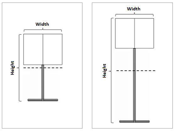
Below is an example of the application of Parametric E resizing:
It is possible to notice that, after changing the height, the dimensions of the extremities remained the same, changing only the height in the middle.
Parametric Middle Using Limit
This resizing is used so that the module can have its dimensions changed considering the measures defined by the limit values, that is, resized by the ends. Quite used for handles, which contains the 0 point of the design in the center.
Application example: Handles.
To apply the resize:
1. Set the resize.
2. Select the Resizing Parametric Medium Using Limit and click OK.
3. Click the Refresh icon to apply the changes.
Below is an example of the application of Parametric E resizing:
It is possible to notice that, after changing the handle width, only the ends were resized, keeping point 0 in the center of the drawing.
