What is a PMOB file?
PMOB is a 3D file format developed by Promob to be used in the Catalog.
What are the advantages of the PMOB file?
The PMOB file format is more complex and complete than the MOB3D format, allowing the loading of objects imported into Promob to be carried out more quickly and safely, improving the performance of Promob in relation to its use and also the image quality from the project.
In addition, this new file format serves as a basis for future improvements to the Promob 3D environment, such as the presentation and rendering of images.
When should a PMOB file be generated?
The PMOB file must be generated whenever a new item is added to the system or when an item has its design changed. However, items that have the old format, continue to function normally.
How to generate a PMOB file?
Relationship between the PMOB file format and the faces of a 3D drawing
Before generating the PMOB file for the modulation items, it is necessary to understand the relationship between this new Promob file format and the faces of a 3D drawing.
Using PMOB implies having a well-behaved design, that is, the faces of the design must face outwards.
Faces are the surfaces of the 3D object. They are usually formed by triangles or by several triangular faces, which form the face of a surface. A face has two sides: the normal (front) side of the face, where the applied materials are displayed and the opposite side of the face, also called "inverted face".
3D drawings with inverted faces generate problems in rendering the object, making the items become transparent in the design, in addition, it is not possible to apply material to faces that are inverted, correction of these faces will be addressed in the items below.
Process of migrating files to PMOB.
The migration process consists of 4 steps:
- Generation of the PMOB file
- Correction of 3D drawing faces
- Checking the faces of the 3D drawing
- Publishing the system
- How to smooth the faces of the 3D drawing?
IMPORTANT:
- The functionalities will only be enabled for modules that have the generated PMOB file.
- The buttons enable active modes, that is, operation mode of the viewport, such as “Select”, “Zoom”, among others.
- When selecting any of the new features, the Module Editor automatically changes the fill mode to “View faces”
Generation of the PMOB file
1. Access the Catalog Module Editor and click on the Design tab. Select the item that will have the PMOB file generated and click on the Generate / Update PMOB button. Enter the smoothing angle of the faces and click Generate. Click here to learn more about face smoothing.
2. Wait while the PMOB file is generated.

3. At the end of the creation of the file, a message is displayed informing about the completion of the generation of the file. Click on OK.

4. After generating the PMOB file, it is necessary to correct the faces of the 3D drawing so that they are not transparent in 3D space. To consult information about the procedure for correcting the faces of the 3D drawing, access the item Correcting the faces of the 3D drawing.
IMPORTANT:
- As the button Generate / Update PMOB remains enabled even after the generation of the PMOB file, it is possible to update the drawing if any changes have been made to the original 3D file.
- In the 2013 version of the Catalog, MOB3D files are no longer generated. When creating a new item or changing a 3D drawing already registered, a PMOB file will be created.
TIP: after generating the PMOB files, use the Orphans - Libraries validator to check the MOB3D files that are no longer used so that they can be removed from the system.
View Faces
The View Faces option displays the faces of the drawing. This functionality does not allow the faces to be inverted and will be enabled only when the selected item has the generated PMOB file. Otherwise, the option is disabled.
1. Access the Module Editor and click on the Drawing tab. The View Faces option is available in fill modes.
2. The faces displayed in gray are normalized. The faces displayed in cyan are inverted.
Correct Faces
The correction of the normals of the drawing faces can be performed automatically only after the generation of the PMOB file.
IMPORTANT: due to the complexity of the 3D object, some normals may not be corrected automatically. Therefore, we recommend that the faces of the drawing be revised through the Module Editor, Design tab.
1. Access the Module Editor and click on the Drawing tab. Click the Correct Faces button, located on the top toolbar.
2. In the message that is displayed, click Yes to confirm the correction of the faces and to finish the correction process, in the message that is displayed click OK.
3. Observe the drawing with its faces corrected. If necessary, use the Invert Faces feature to manually normalize the design faces.

Invert Faces
This option displays the directions of the drawing faces, allowing them to be inverted.
1. Access the Module Editor and click on the Drawing tab. Click the Invert Fix Faces button, located on the top toolbar.

2. The faces shown in gray are normalized. The faces displayed in cyan are inverted. Click with the mouse on the face you want to invert.

TIP: use the movement and visualization tools to view the design from all angles and normalize all of its faces.
Invert Faces Window
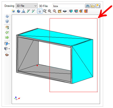
This option has the same function as the “Invert Faces” feature, but operates by the selected area (as in the Zoom Window), and not by clicking the mouse. All faces that are inside the rectangle (displayed in red) will be inverted.
1. Access the Module Editor and click on the Drawing tab. Click the Invert Faces Window button, located on the top toolbar.
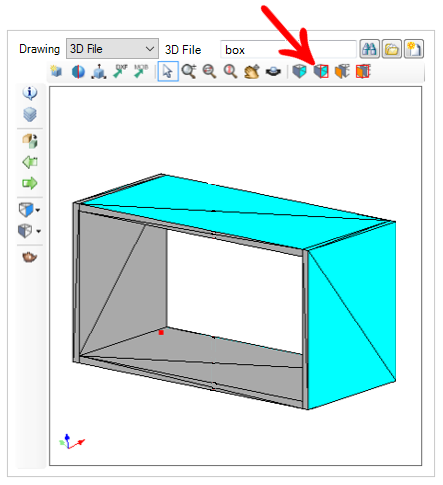
2. Left-click and drag the mouse to create a red window, indicating the area to be selected. Then, release the mouse button and wait while the faces are inverted.
IMPORTANT: all faces that are at least some part of their surface within the area of the rectangle will be inverted. Thus, faces in cyan are displayed in gray and vice versa.
Duplicate Faces
This option works by clicking the mouse, duplicating the clicked face and inverting the copy, without having to open the drawing in 3D modeling software.
In the example below, the top view of the drawing shows the correct side of the object's faces. When looking at the drawing through the bottom view, the inverted faces of the object are displayed. When duplicating the faces of the drawing, new faces are created with the normal ones facing outwards, making the object to be presented with all its faces visible.
1. Access the Module Editor and click on the Drawing tab. Click the Duplicate Faces button, located on the top toolbar.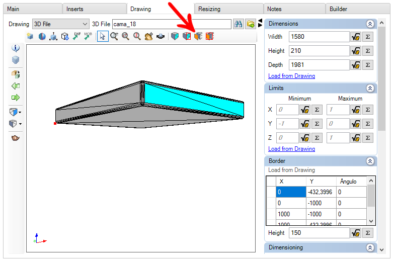
2. Clicking with the mouse on the face you want to duplicate and invert.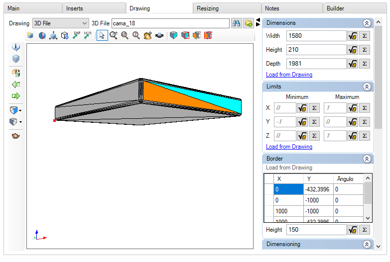
3. Repeat the procedure to duplicate the other faces of the object.
Duplicate Faces Window
This option has the same function as the “Duplicate Faces” feature, but operates by selected area (as in the Zoom Window), and not by clicking the mouse. All faces within the rectangle (shown in red) will be duplicated and inverted.
1. Access the Module Editor and click on the Drawing tab. Click the Duplicate Faces Window button, located on the top toolbar.
2. Left-click and drag the mouse to create a red window, indicating the area to be selected. Then, release the mouse button and wait while the faces are duplicated and inverted.
IMPORTANT: all faces that are at least some part of their surface within the area of the rectangle will be duplicated and inverted.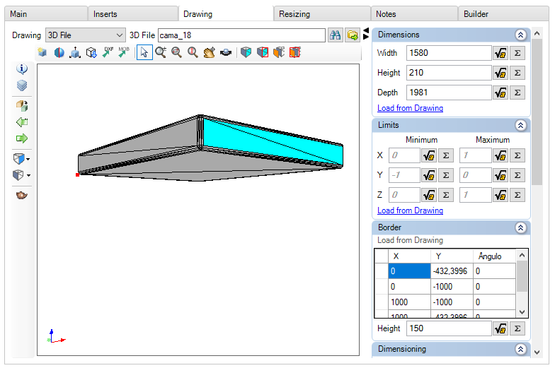
3. All faces that are within the selected area are duplicated and inverted.

Checking the faces of the 3D drawing
This step consists of inserting the module in 3D space after the normalization of its faces. Move the design around so that you can view the module from all angles to verify that all of its faces are correct.
Publishing the system
At the end of the steps above, it is necessary to publish the system so that the changes made can be made available to customers, to consult the step by step of the publication process, click here.