Check below, the settings of each configuration available in the Features Configurator - Offices - Panels. If necessary, see here how to apply the dimension settings.
|
|
General Settings
A – Material: defines the panel material to be used to manufacture the side of the module.
B – Panel maximium width: defines the maximum width of the panel to be used in the fabrication of the module side.
C – Panel maximium length: defines the maximum length of the panel to be used in the fabrication of the module side.
D – Panel thickness: defines the thickness of the panel to be used in the fabrication of the module side.
Side Panel
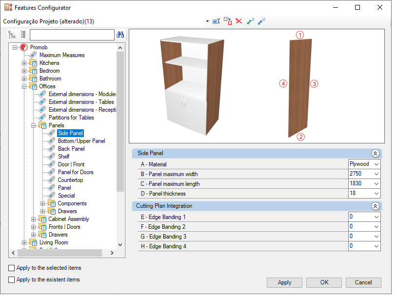
Cutting Plan Integration
E - Edge Banding 1: for cut plans that read the thickness of the edge band, set the thickness to side 1.
F - Edge Banding 2: for cut plans that read the thickness of the edge band, set the thickness to side 2.
G - Edge Banding 3: for cut plans that read the thickness of the edge band, set the thickness to side 3.
H - Edge Banding 4: for cut plans that read the thickness of the edge band, set the thickness to side 4.
Bottom/Upper Panel
Cutting Plan Integration
E - Edge Banding 1: for cut plans that read the thickness of the edge band, set the thickness to side 1.
F - Edge Banding 2: for cut plans that read the thickness of the edge band, set the thickness to side 2.
G - Edge Banding 3: for cut plans that read the thickness of the edge band, set the thickness to side 3.
H - Edge Banding 4: for cut plans that read the thickness of the edge band, set the thickness to side 4.
Back Panel
Cutting Plan Integration
E - Edge Banding 1: for cut plans that read the thickness of the edge band, set the thickness to side 1.
F - Edge Banding 2: for cut plans that read the thickness of the edge band, set the thickness to side 2.
G - Edge Banding 3: for cut plans that read the thickness of the edge band, set the thickness to side 3.
H - Edge Banding 4: for cut plans that read the thickness of the edge band, set the thickness to side 4.
Shelf
Cutting Plan Integration
E - Edge Banding 1: for cut plans that read the thickness of the edge band, set the thickness to side 1.
F - Edge Banding 2: for cut plans that read the thickness of the edge band, set the thickness to side 2.
G - Edge Banding 3: for cut plans that read the thickness of the edge band, set the thickness to side 3.
H - Edge Banding 4: for cut plans that read the thickness of the edge band, set the thickness to side 4.
Door | Front
Cutting Plan Integration
E - Edge Banding 1: for cut plans that read the thickness of the edge band, set the thickness to side 1.
F - Edge Banding 2: for cut plans that read the thickness of the edge band, set the thickness to side 2.
G - Edge Banding 3: for cut plans that read the thickness of the edge band, set the thickness to side 3.
H - Edge Banding 4: for cut plans that read the thickness of the edge band, set the thickness to side 4.
Manufacturing Process
I - Manufacturing Process Quantity: defines whether the manufacturing process will be budgeted in units or in meters. Exclusive option for doors with differente cutout.
Panel for Doors
Glass Panel
A - Panel maximium width: defines the maximum glass width to be used in module manufacturing.
B - Panel maximium length: defines the maximum length of the glass to be used in the manufacturing of the module.
C - Glass Thickness: defines the thickness of the glass to be used in the manufacturing of the module.
Countertop
Cutting Plan Integration
E - Edge Banding 1: for cut plans that read the thickness of the edge band, set the thickness to side 1.
F - Edge Banding 2: for cut plans that read the thickness of the edge band, set the thickness to side 2.
G - Edge Banding 3: for cut plans that read the thickness of the edge band, set the thickness to side 3.
H - Edge Banding 4: for cut plans that read the thickness of the edge band, set the thickness to side 4.
Panel
Cutting Plan Integration
E - Edge Banding 1: for cut plans that read the thickness of the edge band, set the thickness to side 1.
F - Edge Banding 2: for cut plans that read the thickness of the edge band, set the thickness to side 2.
G - Edge Banding 3: for cut plans that read the thickness of the edge band, set the thickness to side 3.
H - Edge Banding 4: for cut plans that read the thickness of the edge band, set the thickness to side 4.
Special
A - Panel maximium width: defines the maximum panel width to be used in the module's manufacturing.
B – Panel maximium length: defines the maximum panel length to be used in module manufacturing.
C - Panel thickness: defines the thickness of the panel to be used in the manufacturing of the module.
Components
Cleats
Cutting Plan Integration
E - Edge Banding 1: for cut plans that read the thickness of the edge band, set the thickness to side 1.
F - Edge Banding 2: for cut plans that read the thickness of the edge band, set the thickness to side 2.
G - Edge Banding 3: for cut plans that read the thickness of the edge band, set the thickness to side 3.
H - Edge Banding 4: for cut plans that read the thickness of the edge band, set the thickness to side 4.
Kick Plate
Cutting Plan Integration
E - Edge Banding 1: for cut plans that read the thickness of the edge band, set the thickness to side 1.
F - Edge Banding 2: for cut plans that read the thickness of the edge band, set the thickness to side 2.
G - Edge Banding 3: for cut plans that read the thickness of the edge band, set the thickness to side 3.
H - Edge Banding 4: for cut plans that read the thickness of the edge band, set the thickness to side 4.
Overlay Fillers
Cutting Plan Integration
E - Edge Banding 1: for cut plans that read the thickness of the edge band, set the thickness to side 1.
F - Edge Banding 2: for cut plans that read the thickness of the edge band, set the thickness to side 2.
G - Edge Banding 3: for cut plans that read the thickness of the edge band, set the thickness to side 3.
H - Edge Banding 4: for cut plans that read the thickness of the edge band, set the thickness to side 4.
Panel Foot
Cutting Plan Integration
E - Edge Banding 1: for cut plans that read the thickness of the edge band, set the thickness to side 1.
F - Edge Banding 2: for cut plans that read the thickness of the edge band, set the thickness to side 2.
G - Edge Banding 3: for cut plans that read the thickness of the edge band, set the thickness to side 3.
H - Edge Banding 4: for cut plans that read the thickness of the edge band, set the thickness to side 4.
Honeycomb Sandwich Moulding
Cutting Plan Integration
E - Edge Banding 1: for cut plans that read the thickness of the edge band, set the thickness to side 1.
F - Edge Banding 2: for cut plans that read the thickness of the edge band, set the thickness to side 2.
G - Edge Banding 3: for cut plans that read the thickness of the edge band, set the thickness to side 3.
H - Edge Banding 4: for cut plans that read the thickness of the edge band, set the thickness to side 4.
Drawers
Side Panel
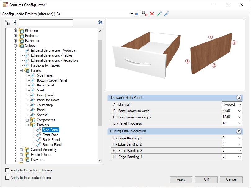
Cutting Plan Integration
E - Edge Banding 1: for cut plans that read the thickness of the edge band, set the thickness to side 1.
F - Edge Banding 2: for cut plans that read the thickness of the edge band, set the thickness to side 2.
G - Edge Banding 3: for cut plans that read the thickness of the edge band, set the thickness to side 3.
H - Edge Banding 4: for cut plans that read the thickness of the edge band, set the thickness to side 4.
Front Face
Cutting Plan Integration
E - Edge Banding 1: for cut plans that read the thickness of the edge band, set the thickness to side 1.
F - Edge Banding 2: for cut plans that read the thickness of the edge band, set the thickness to side 2.
G - Edge Banding 3: for cut plans that read the thickness of the edge band, set the thickness to side 3.
H - Edge Banding 4: for cut plans that read the thickness of the edge band, set the thickness to side 4.
Back Panel
Cutting Plan Integration
E - Edge Banding 1: for cut plans that read the thickness of the edge band, set the thickness to side 1.
F - Edge Banding 2: for cut plans that read the thickness of the edge band, set the thickness to side 2.
G - Edge Banding 3: for cut plans that read the thickness of the edge band, set the thickness to side 3.
H - Edge Banding 4: for cut plans that read the thickness of the edge band, set the thickness to side 4.
Bottom Panel
Cutting Plan Integration
E - Edge Banding 1: for cut plans that read the thickness of the edge band, set the thickness to side 1.
F - Edge Banding 2: for cut plans that read the thickness of the edge band, set the thickness to side 2.
G - Edge Banding 3:for cut plans that read the thickness of the edge band, set the thickness to side 3.
H - Edge Banding 4: for cut plans that read the thickness of the edge band, set the thickness to side 4.