The AngleBetweenEdgesPMOB attribute is equivalent to the AngleBetweenEdges used for the old MOB3D drawing file format. As of the 2013 version of Promob, a new design file extension, the PMOB extension, was created.
AngleBetweenEdgesPMOB attribute definitions.
Register the AngleBetweenEdgesPMOB attribute.
Correct Triangulated Faces with AngleBetweenEdgesPMOB
AngleBetweenEdgesPMOB attribute definitions
This attribute hides lines from drawings that use the PMOB format, minimizing the number of visible edges in the line fill modes. It checks using the angles formed between the normals of the two faces. Its default value is 10.
Taking the image below as an example, we have a 90 ° angle formed by the normals of the upper and left faces. When generating the PMOB, the edges are drawn between the faces that form an angle bigger than the specified angle.

When registering this attribute, its default configuration defines that it is created automatically (in a hidden way) for all entities (Automatic Creation property) and with a default value of 10, that is, the attribute is applied in all modules in order to decrease the number of lines and remove excess lines. If it is necessary to increase the number of lines, you must apply the attribute in the module and change its value to a lower value.
Example:
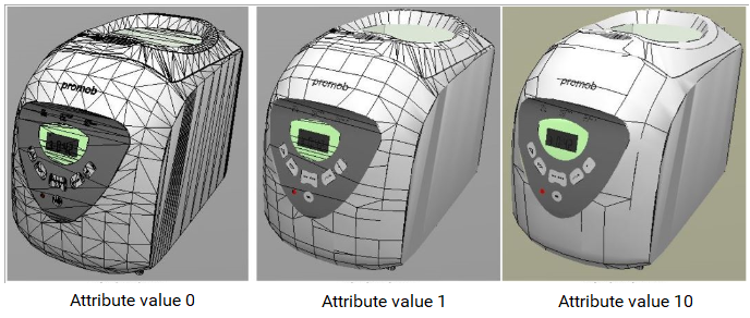
In a drawing that contains many triangulated faces, the attribute can be applied to improve the presentation of the module.
In the images below, on the left, it is possible to notice that with the AngleBetweenEdgesPMOB attribute with a value of 0, the module presents itself with many lines. In the center, with the attribute AngleBetweenEdgesPMOB with value 1, the number of lines decreases, and, on the right with the value 10, it is noticed that the number of lines is much less than the initial quantity.
Register the AngleBetweenEdgesPMOB attribute.
1. Access the Registry - System - Attributes menu.
2. In Entity attributes, click the Design group.
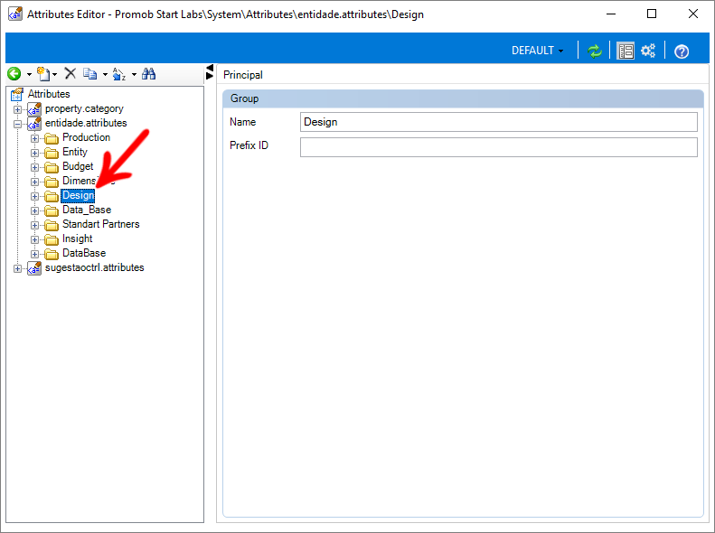
3. Click Add Attribute and select the Create Attribute option.

4. In the entity attribute record, define.
ID: AngleBetweenEdgesPMOB
Nome: Edge design for PMOB

5. Click OK.
6. Then fill in the following fields:
- Description: Draw Edges shared by multiple faces based on a minimum angle to compare normals for PMOB
- Category: Design
- Type: Decimal Number
- Default value: 10
In the Parameters grouping check the Editable option
In the Behavior grouping check the option Automatic creation
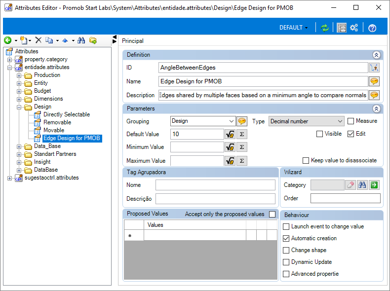
7. After completing the registration of the attribute, click Refresh, in the header. 
8. After registering the attribute, you can apply the attribute. Click here to check the procedure
Correct Triangulated Faces with AngleBetweenEdgesPMOB
Sometimes after registering a module with a drawing, when inserting the item in the 3D environment, it is displayed with triangulated faces, with a diagonal line on each face:

To correct drawings with triangulated faces:
1. Access the Registry - Modules menu.
2. Locate the module that contains the associated drawing in the Navigation Tree.
Example: If it is the door handle, access the handle register, where its design is associated.
3. On the Main tab, access the Attributes tab and click on the Find icon.
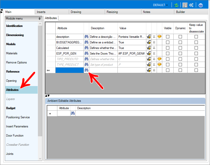
4. Locate and apply the ANGLEBETWEENEDGESPMOB attribute by clicking OK.
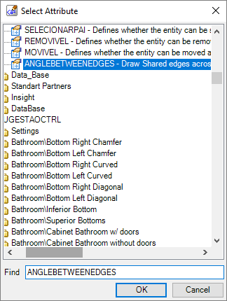
5. The attribute will be added with the default value 10. Keep the default value.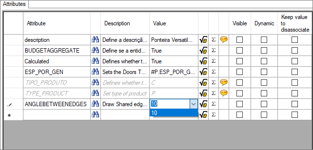
6. After making changes, click the Refresh icon in the header. 
