Check below the specifications and configurations available in the ABD 100 plugin:
Available from version:Plugin Builder 1.60.17.4
Machine Type: CNC Machining Center
Manufacturer: Weeke / Homag
Programs example: COM2591A
Generated file extension: .mpr
Manual: manual available for the manufacturer, click here.
Main features
- Holes
- Hardware inserts (Dowel pin, wedges, Drawer runners). For more information about hardware insert registration, please visit the article Builder - Hardware Insert Registration.
Settings
To check the settings on CNC Machines, click here.
Machine 1
General
Name: define the name for the machine.
IMPORTANT: The name set in this field also changes the name of the folder where the generated files will be saved.
Generator ID: machine generator ID;
Length X (mm): length of the machine;
Min Length X (mm): minimum thickness of the part that the machine can perform operations;
Width Y (mm): width of the machine;
Max thickness Z (mm): machine maximum supported thickness (Z);
Min thickness Z (mm): machine minimum supported thickness (Z);
Variable usage field distance, in X axis: distance relative to the end bound in X axis, which determines the area, where operations must consider the piece size variable minus the operation distance from end bound;
Variable usage field distance, in Y axis: distance relative to the end bound in Y axis, which determines the area, where operations must consider the piece size variable minus the operation distance from end bound;
Inverter variable fields: if this option marked, when a rotated piece is generated, the variable fields are inverted.
Rotations
Evaluate minimum width for rotation: defines whether the minimum dimensions of the part to be rotated in the length direction will be evaluated in the generation of the programs. If yes, pieces that have a face smaller than the defined size will be rotated, they will have this face aligned to the axis of the width of the machine;
Minimum length allowed for rotations (mm): define the minimum length allowed to perform rotations. If length is lower than the defined, the piece's higher dimension will be put in X.
.Inf File
Detail all programs operations: detail all programs (A, B, C…) invalid operations on file .inf;
Generate empty parts inf: Generate empty parts info.
Holes and hardware insertions
Marking hole depth (mm): maximum depth to be considered marking hole. When the hole is smaller or equal, it will automatically be considered a marking hole;
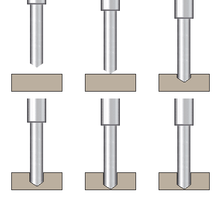
Non-through drilling mode: drilling mode for non-passing holes in the part;

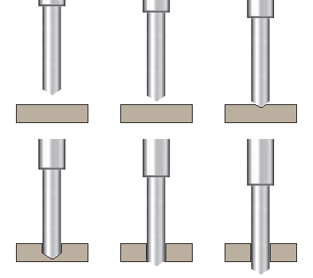
Through drilling mode: drilling mode for through holes in the part;

Drilling and hardware insertion minimum diameter: minimum diameter for drilling and hardware insertion.
Lateral holes and hardware insertions
Maximum diameter for lateral drilling and hardware insertion (mm): maximum diameter for drilling and inserting side hardware;
Maximum lateral hole and hardware insertion depth (mm): maximum depth for drilling and inserting side hardware;
Number of lateral drilling to each lateral: number of drill bits for side drilling on each side (on the top faces).

Vertical holes and hardware insertions
Maximum diameter for vertical drilling and hardware insertions (mm): maximum diameter for drilling and inserting vertical hardware;
Maximum vertical hole and hardware insertion depth (mm): Maximum drilling and insertion depth for vertical hardware;
Number of vertical drilling: number of drill bits for vertical drilling (on the top face);
Minimum position by the center of the tool for vertical drilling and Hardware: minimum position in the center of the tool for drilling and inserting hardware verticals in Y.

Set-Ups
General
Name: the name set in this field also changes the name of the folder where the generated files will be saved.
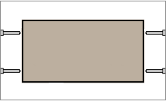
Alignment by face: defines whether the alignment face registered on each part is considered when generating programs. If yes, this face will be aligned according to the selected configuration. For more information click here.
Make Holes: the machine is able to drill holes;
Make hardware insertions: the machine is able to do the hardware insertion;
Selected process for hardware insertions: process selected for the machine to do hardware insertion.
Machine
Priorization order: defines the order of prioritization of operations for program generation. According to the order indicated in this field, the plugin will prioritize, in program A, the selected option.
Example: In a part that has holes on one side and tears on the other side, the order indicated in this field will determine which of them will be prioritized in the A program.
Operations order: order that the machine performs operations.
Holes
Normal hole drill type: drill option for normal drilling. Drilling is considered normal when it is not through or marking;
Through hole drill: drill bit options for through hole drilling;
Marking holes drill: drill bit option for marking drilling;
Gap for through drilling (mm): determines the clearance of the drill for use in through holes;
Drill angle for through drilling: determines the drill angle for through hole drilling (from 25 to 90 angle).