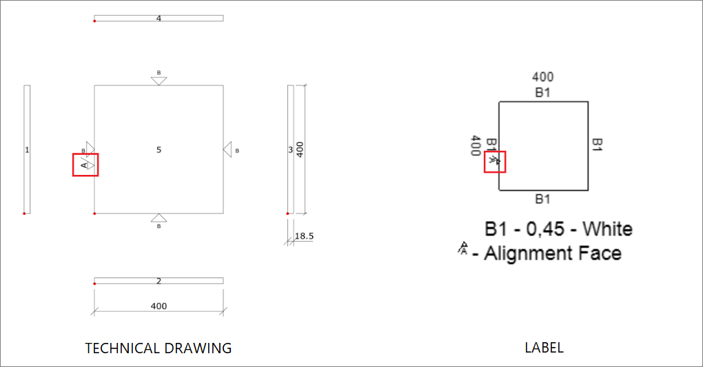
Within the Builder generated files, technical drawings (PDF), and label images, all parts that have a registered alignment face receive the symbol A, as shown in the image below:

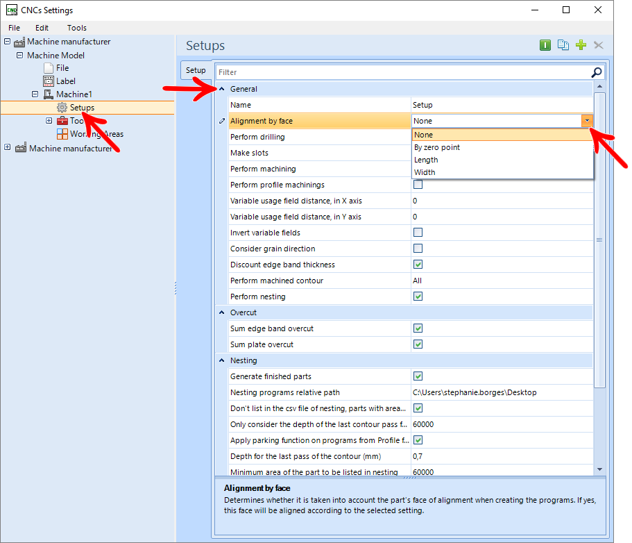
The alignment face can be better translated as the edge of the part that will touch the "origin" (zero-point) of the machine, but it all depends on how the Align by face field was configured in the CNC Plugin, detailed below.

By point zero

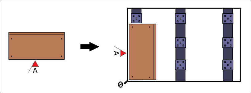
EXAMPLE:

This configuration causes the alignment face to be in contact with the zero-point of the machine, there are 2 possible positions, as the alignment face can be both in the length and in the width direction of the machine table. In practice, in vertical machines, for example, the part may be with the alignment face or downwards, or to the right (in both cases, the machine origin is in contact with the alignment face of the part).
This is the most used and recommended option, since, with 2 possible positions per face, it generates fewer physical machine restrictions and prevents possible clearances or CNC alignment errors from becoming very apparent in the finished unit, because, by default, the alignment face is the front edge of the parts, so any difference in machining will go to the bottom of the mobile.
None

EXAMPLE:

With this option, the plugin will ignore the part alignment face so that it is rotated in a way that can perform the greatest amount of operations in a single program.
Length

EXAMPLE:

This configuration makes the alignment face obligatorily parallel to the “length” of the machine table, for example: on vertical machines, the alignment face would be downwards.
Leaving it in this configuration maintains a pattern of placement between all parts, however, it can cause some physical restrictions with the machine, as in this case, there will only be 1 possible position on each side of the part.
In the case of a base (with front alignment), if it is designed for a small width, the part will not be rotated at the CNC, because this setting will force its alignment to be at length.
Width

EXAMPLE:

This setting is ultimately similar to the Length setting however in this case the alignment face will be parallel to the width (or height) of the machine table.
Topple
In cases where the part has holes on both sides, which generates programs A and B, it is necessary to tip the part on the machine, in order to carry out program B.
The general rule is that, when performing the toppling, the initial alignment face must face the same side as it was, therefore, if the alignment is to the length (of the machine table), the tipping must be done in the horizontal direction. If the alignment face is in the width/height (of the machine table), the toppling must be done in the vertical direction.
GENERAL OBSERVATIONS:
Promob generates the technical PDF drawings and labels in a standard way.
Therefore, visually, it should not be based on the drawing provided by Promob for positioning the part on the machine, the information it provides that is relevant for positioning is the edge that is the alignment face.
To find out if the part will be vertical or horizontal, you can open the program in a specific software from the manufacturer e.g (Biesse Works, Xilog, Maestro, WoodWop….), so it will be possible to check through the part design in these programs, how will the meaning of it be.
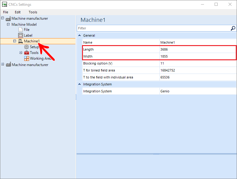
For the Length and Width values, not necessarily, the larger value will be the Length and the smaller one will be the Width. This will be defined in the Machine Configuration (CNC), as shown below:
EXAMPLE:

If you have questions on how to change the alignment face in library compositions, go to Builder - Change alignment face in compositions