In the print prototype is available the option Automatic Documentation prototype, Promob generates the project documentation automatically, with viewport with floor plan view and with detailed view of the project with their respective quotas.
To generate automatic documentation
1. Go to Print in the top bar.
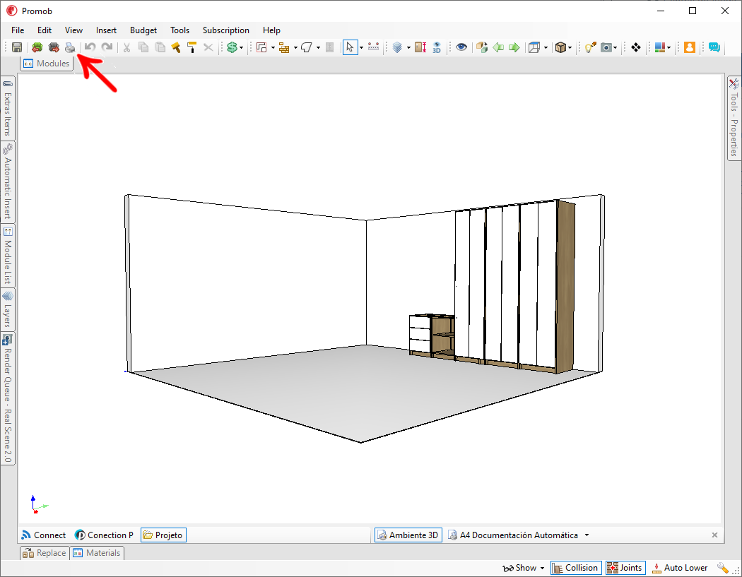
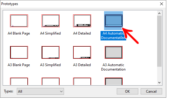
2. Under Prototypes, select Automatic Documentation, and click OK.
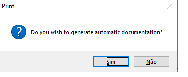
3. In the warning message, click Yes to confirm the automatic documentation generation.
4. In the Automatic Documentation screen, make the desired settings and click OK:
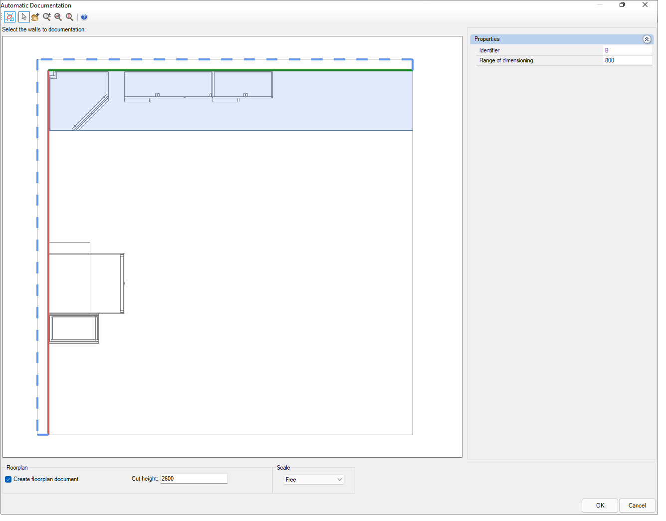
5. On the top bar set:
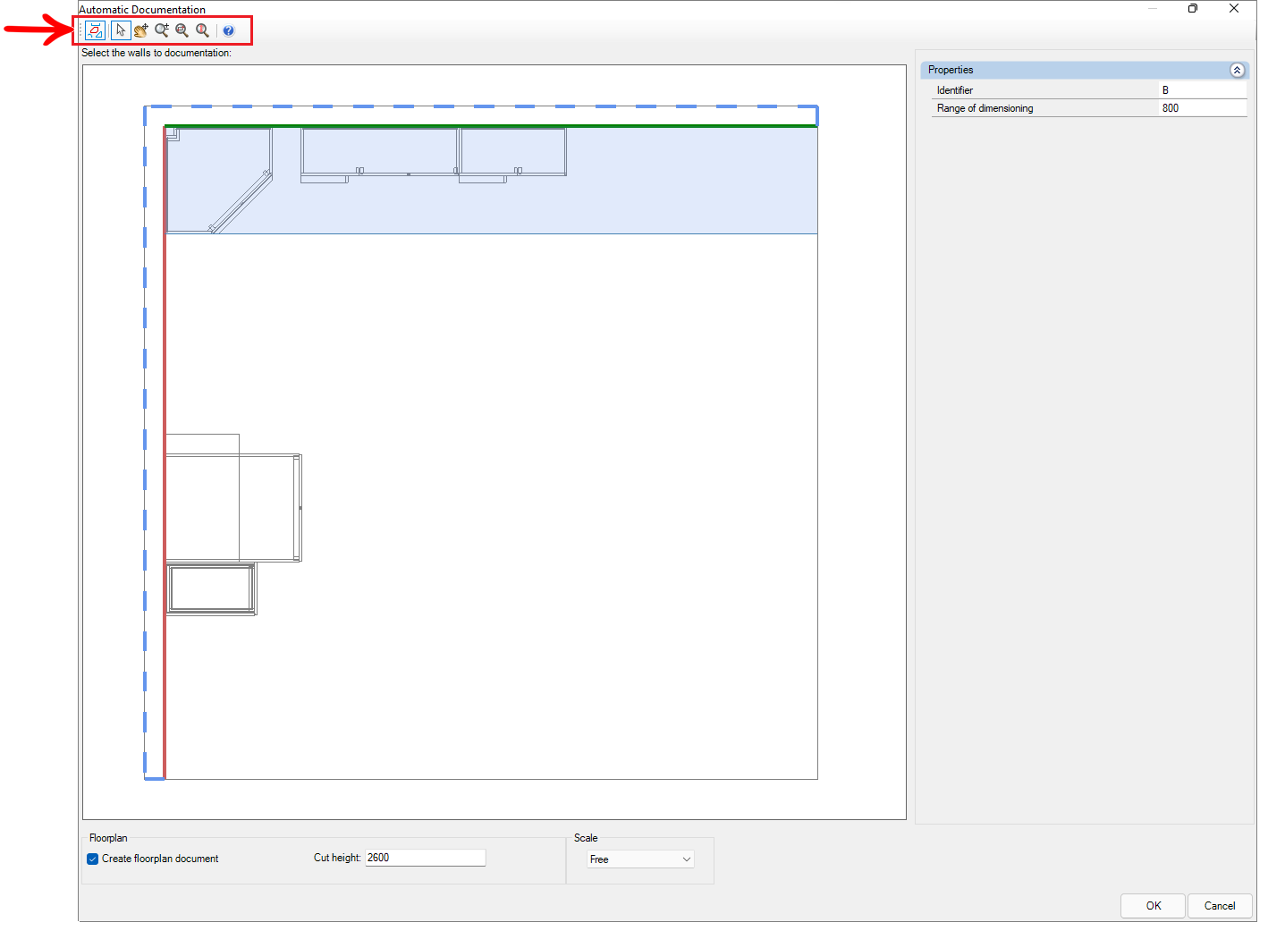
- Show items near
 : when enabling the neighboring modules will be displayed in the view.
 - Select
 : selects and moves items on the Automatic Documentation page.
 - Pan
 : moves the item on the Automatic Documentation page.
 - Zoom
 : zooms in or out of the environment on the Automatic Documentation page.
 - Zoom window: zooms into a region selected by the user on the page.
- Total Zoom: frames the entire environment on the page.
- Help: takes you to the Promob support page about print prototypes.
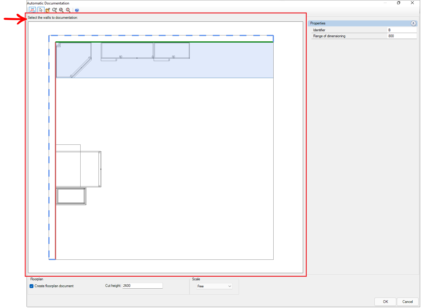
6. In the Select the walls to documentation, click on the desired wall to generate the Automatic Documentation.
7. In Properties set:
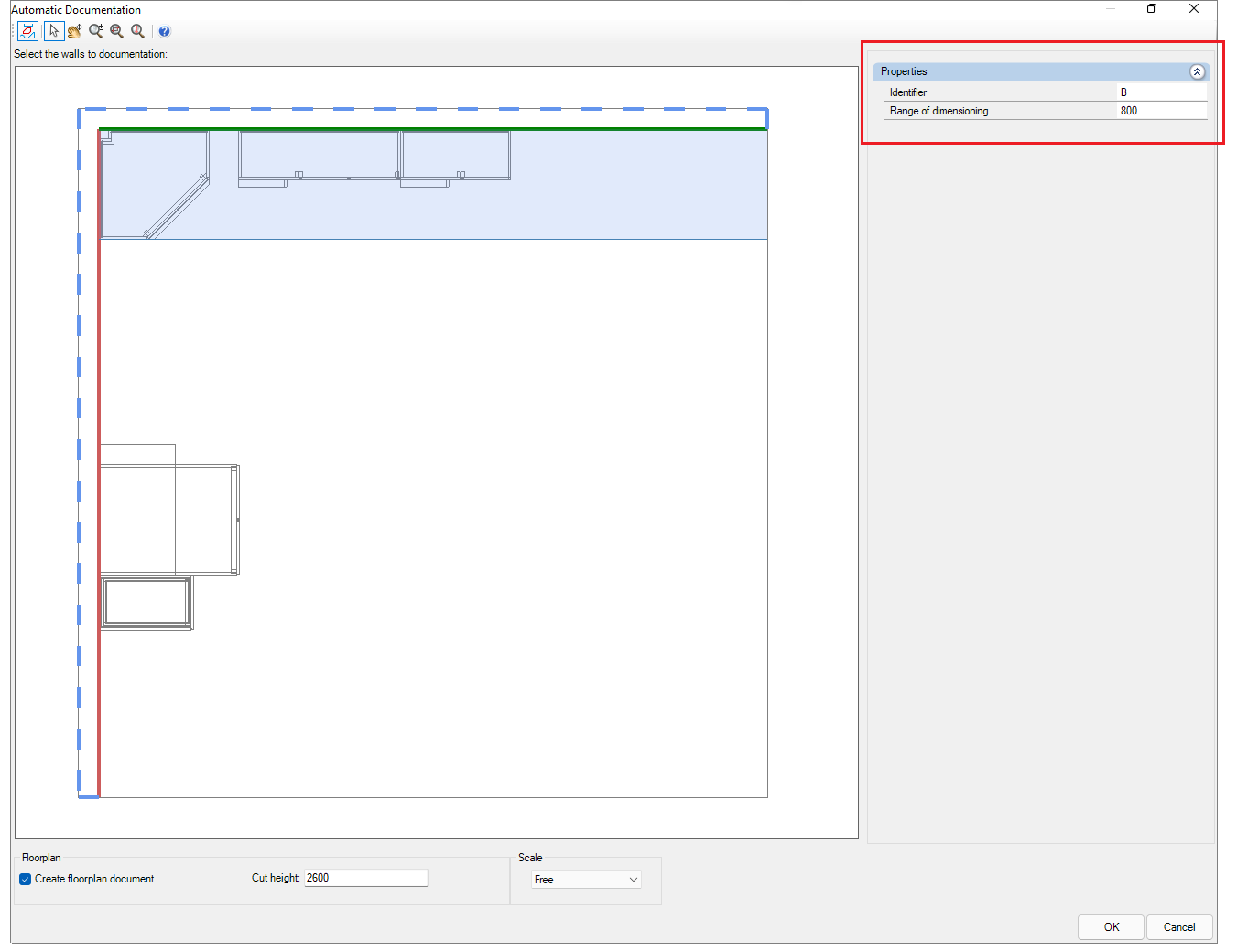
- Identifier: is a name used to identify which wall is being documented. For example, if there are two walls, "A" can be renamed to "X" and "B" to "Y".
- Range Dimensioning: define how far the dimension is from the module for automatic dimensioning.
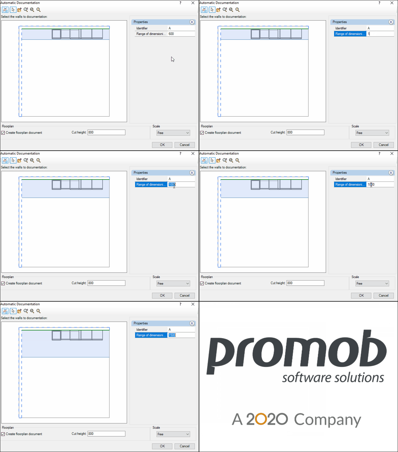
IMPORTANT:
- As of Promob version 5.60.16.77 the default value of the Range Dimensioning, is the value respective to the module with the greatest depth located parallel to the selected wall.
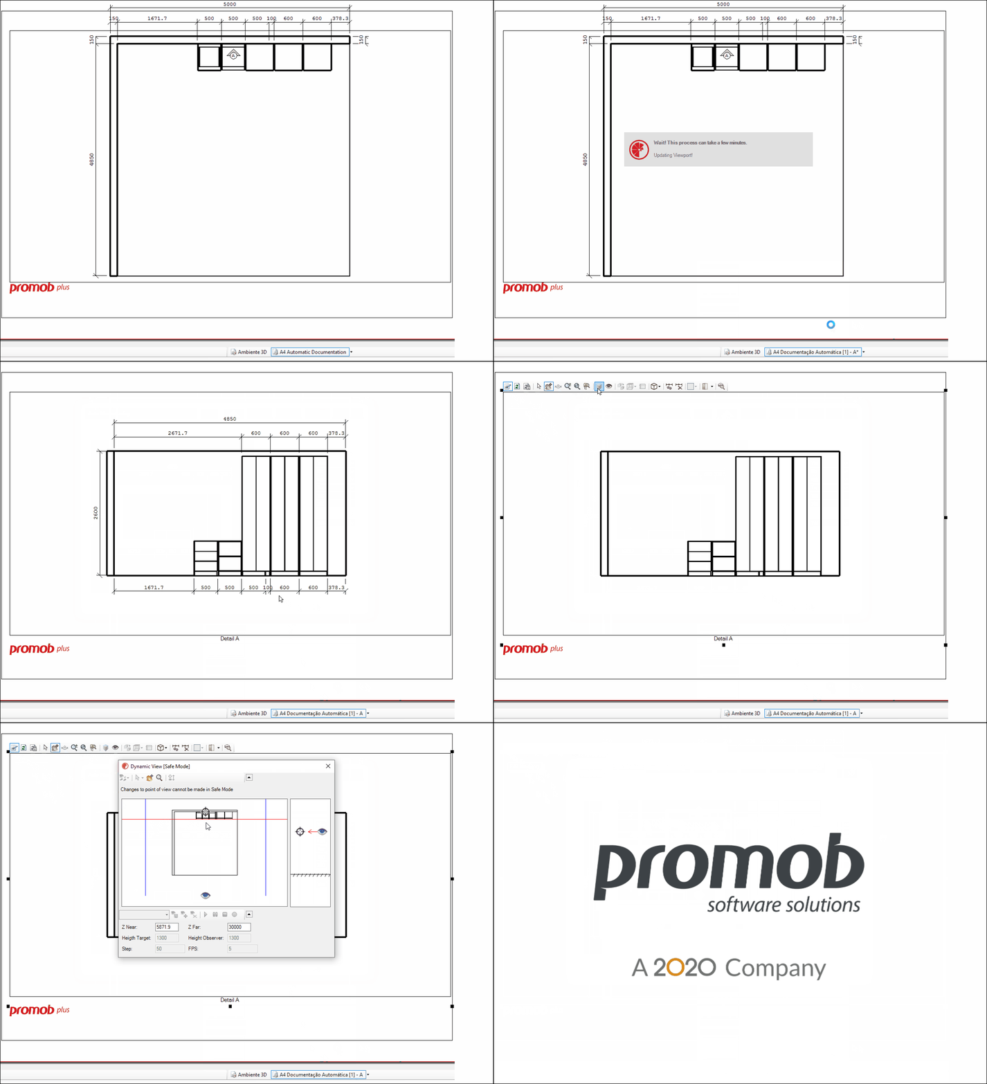
- Starting with Promob version 5.60.16.77, when you open the Dynamic View in the Viewport in the Automatic Documentation, it will be in the position defined here in the Range Dimensioning.
For example:
8. In Floorplan, define:
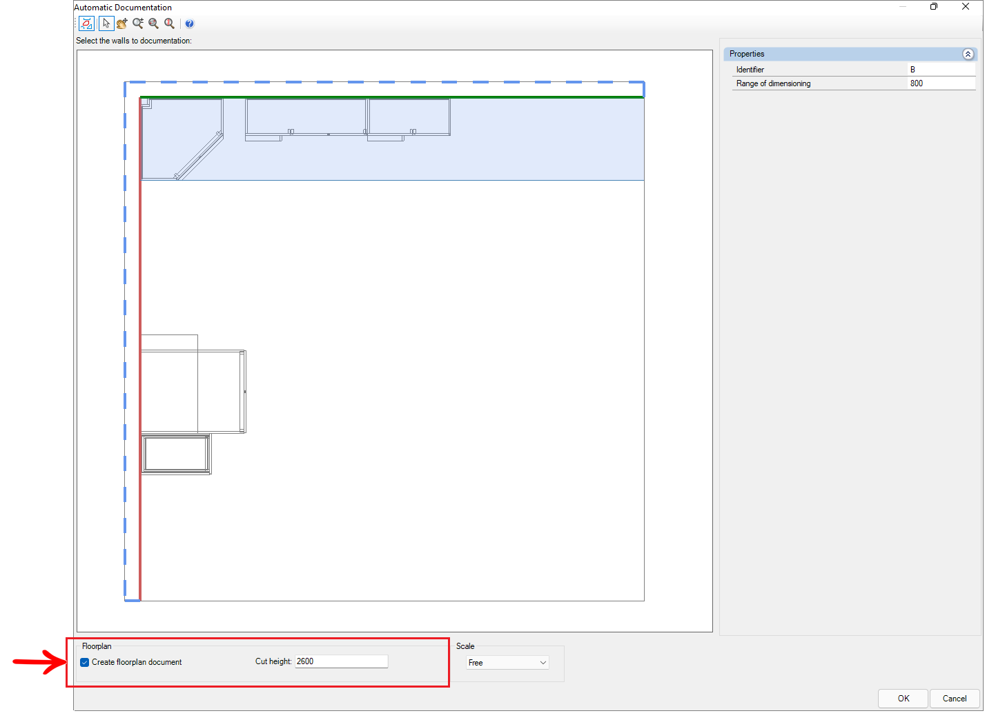
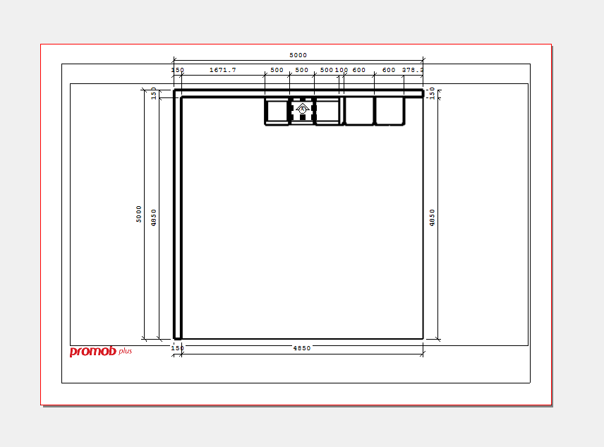
- Create floorplan document: selecting this option generates the floor plan view with dimensions in the Automatic Documentation.
Example of Automatic Documentation Floorplan:
- Cut Height: Define the height you want to make the cut for generating the floor plan view.
IMPORTANT: The default value of Cut Height is equal to the value of the greatest height between the wall(s) contained in the 3D environment. The maximum acceptable value in the field is the default value.
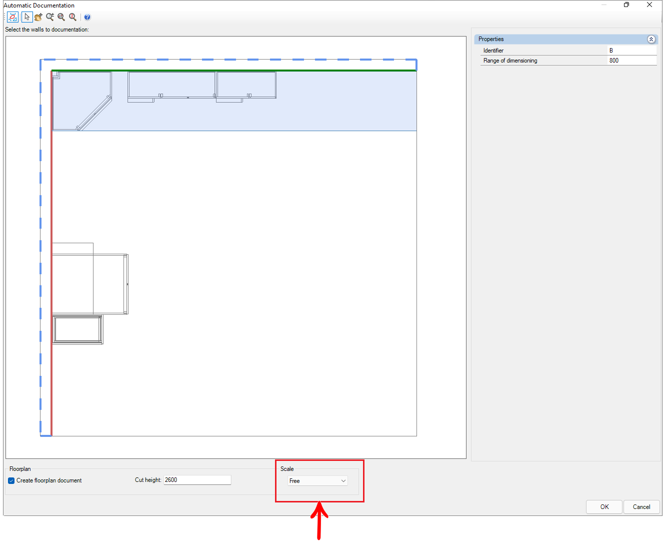
9. In Scale, define which scale the automatic documentation will be generated.
10. After clicking OK, the Auto Dimensioning screen for the floor plan appears, make the desired settings:
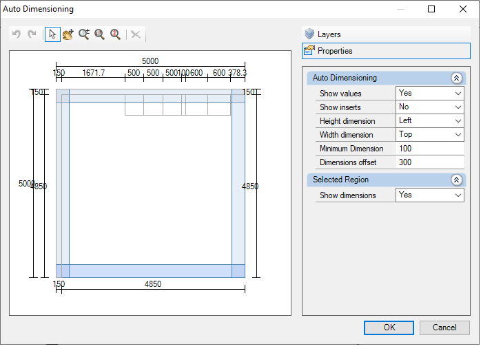
10.1 In Layers, select the layers from which libraries dimensions will be displayed in the Automatic Documentation for the floor plan.
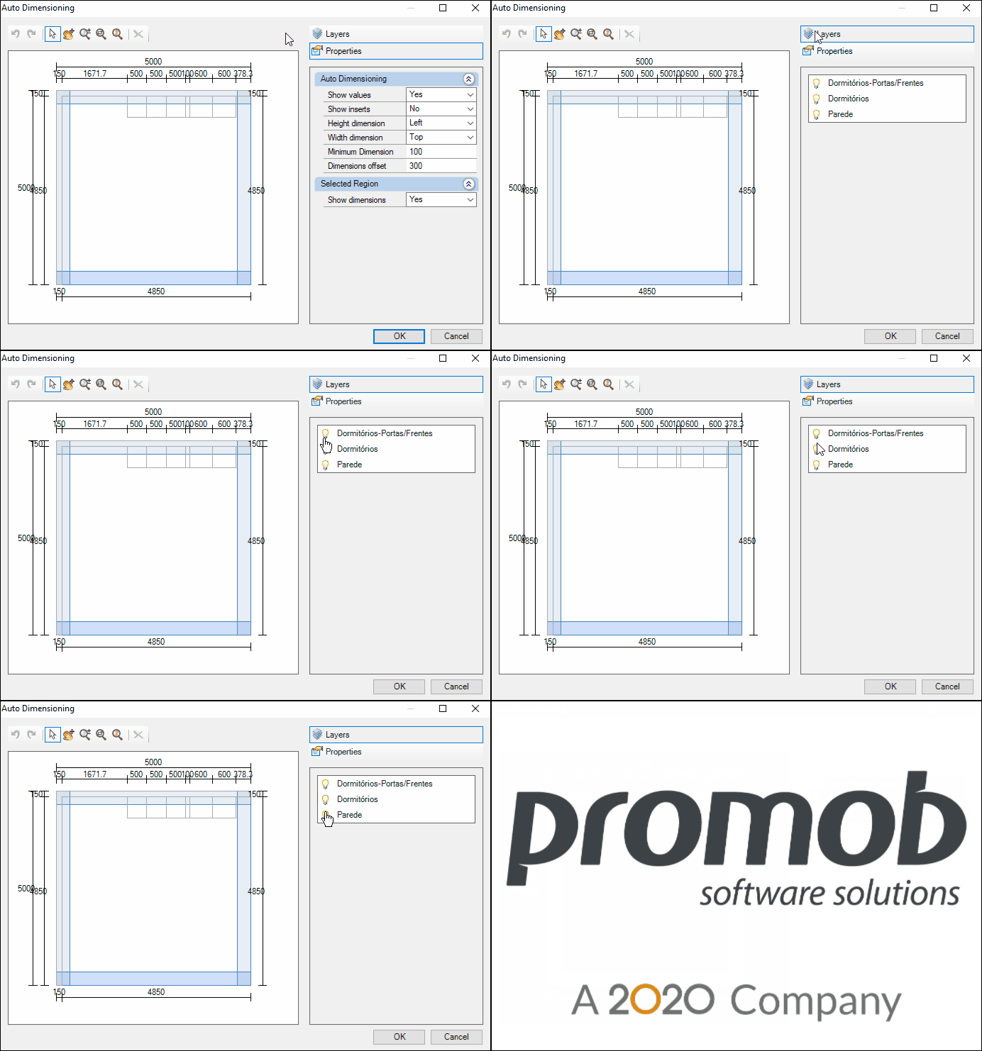
10.2. Under Properties, set:
- Auto Dimensioning:
- Show Values: Select Yes, the value of the dimensions is displayed. Select No, and the dimension value is not displayed.
- Show Inserts: Select Yes, the aggregates are quoted. Select No, and the aggregates are not quoted.
- Height dimension: Set on which side (none, left, right) the height dimension of the respective image is displayed.
- Width dimension: define on which side (none, top, bottom) the dimension referring to the respective image's width will be displayed.
- Minimum dimension: only dimensions above this value will be shown.
- Dimension Offset: Set the offset distance at which dimensions are displayed from the walls.
- Selected Region
- Show dimensions: Select the desired wall to Yes display dimensions on the wall, or No display dimensions on the wall.
10.3. Click OK, then the Automatic Floorplan Documentation appears.
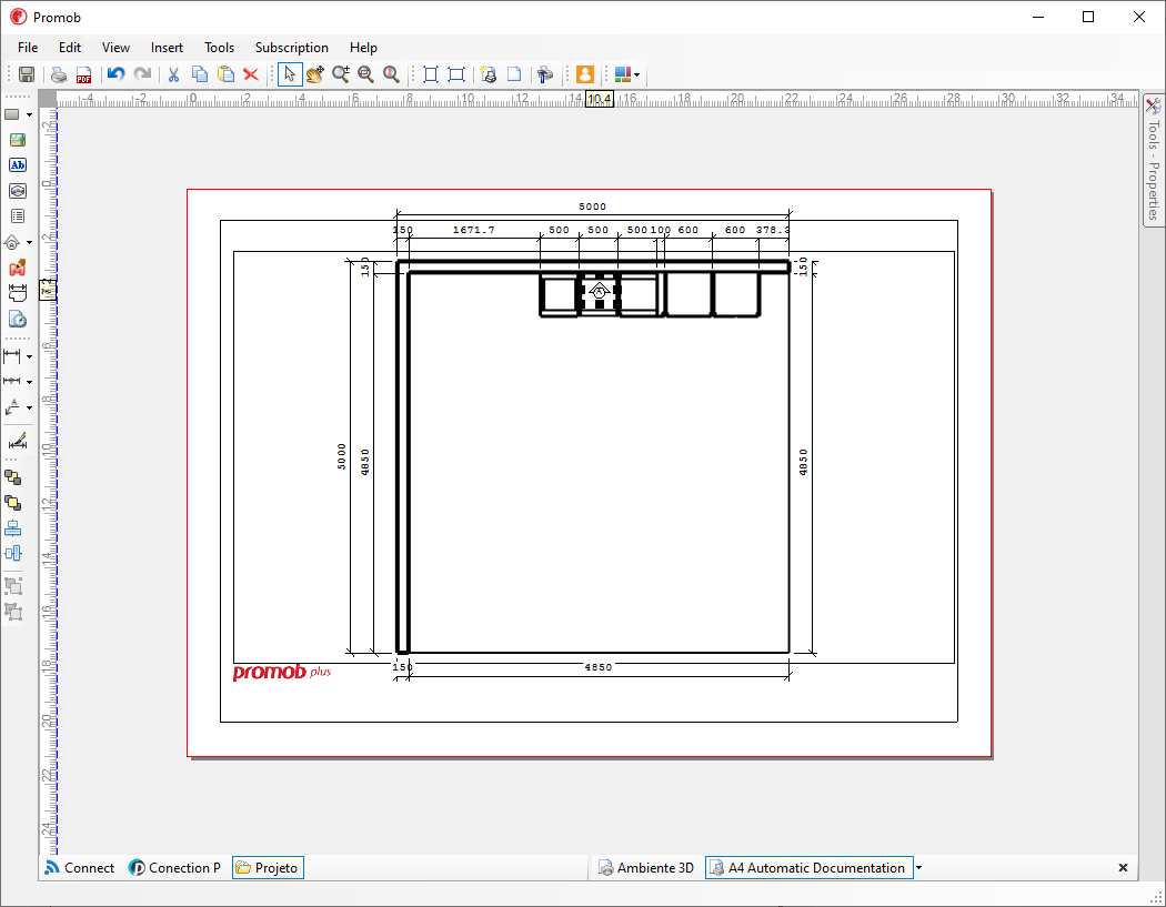
11. To view the Automatic Documentation for the detail view, go to the project attachments tab, and wait for the viewport to be updated.
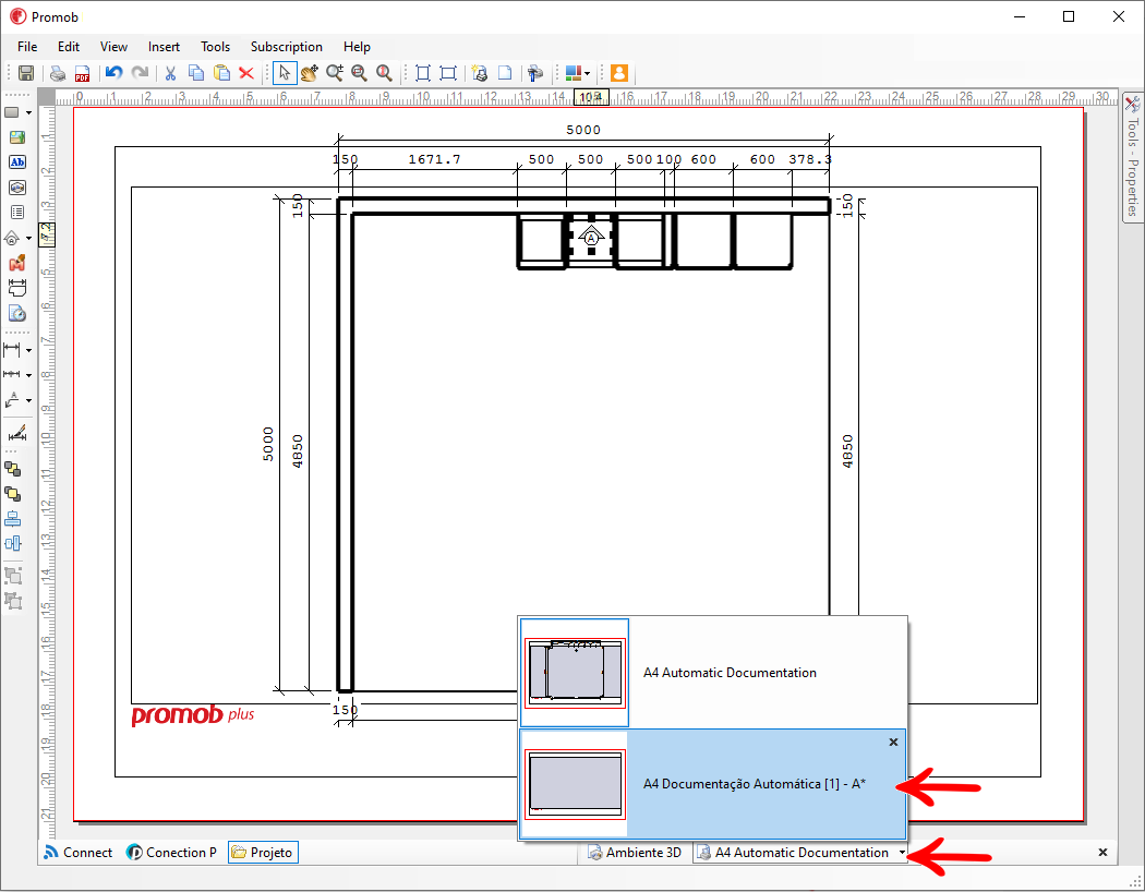
12. The Auto Dimensioning screen appears with the detail view, make the desired settings:
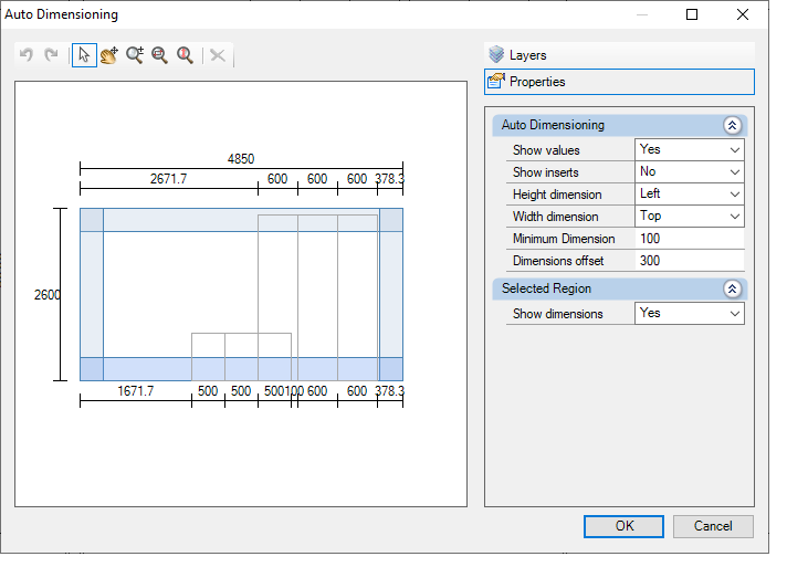
12.1. In Layers, select the layers from which libraries dimensions will be displayed in the Automatic Documentation for the floorplan.
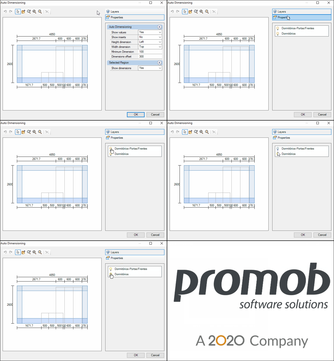
12.2. Under Properties, set:
- Auto Dimensioning:
- Show Values: Select Yes, the value of the dimensions is displayed. Select No, and the dimension value is not displayed.
- Show Inserts: Select Yes, the aggregates are quoted. Select No, and the aggregates are not quoted.
- Height dimension: Set on which side (none, left, right) the height dimension of the respective image is displayed.
- Width dimension: define on which side (none, top, bottom) the dimension referring to the respective image's width will be displayed.
- Minimum dimension: only dimensions above this value will be shown.
- Dimension Offset: Set the offset distance at which dimensions are displayed from the walls.
- Selected Region
- Show dimensions: Select the desired wall to Yes display dimensions on the wall, or No display dimensions on the wall.