Insert the viewport
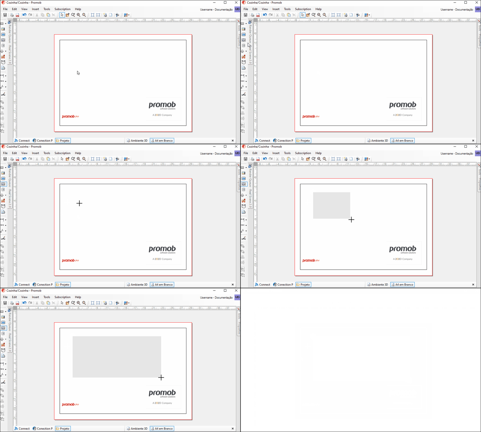
1. Click the viewport  button on the side toolbar;
2. Click at a location on the page to define the start of the viewport;
3. Move the mouse (without pressing it). Click somewhere else to define the end of the viewport;
4. The image of the 3D environment is displayed in the viewport.
Edit the viewport
1. Select the viewport and click the Edit Viewport ![]() button;
button;
2. The viewport toolbar is activated;
3. The tools for editing the viewport are:
| Icon | Description | How to use the tool |
| Update: updates viewport according to the 3D environment. | Click the button. | |
| Block update: when you block the viewport from being refreshed, the viewport will print the way it looks on the print page. | Click the button to freeze the viewport and disable all view editing options. | |
| Select/Move: selects and moves regions. | Click on the region, which is displayed in red lines, and move it. | |
| Pan: Moves the environment on the Editor screen. | Hold down the mouse scroll button while moving the pointer over the graphics area to perform the move. | |
| Rotate: creates a free rotation axis for the project. | Hold down the scroll button and also the left mouse button and drag from side to side or up and down. | |
| Zoom: zooms in or out of the environment on the Editor screen. | Position the mouse over the location or item in the environment that you want to zoom in or out. Hold down the mouse button as you move the pointer over the graphics area upwards to zoom in, or downwards to zoom out. | |
| Zoom Window: Zooms in on a region of the environment selected by the user on the Editor screen. | Left-click and drag the mouse to create a red window indicating the area that will be zoomed in. Release the mouse button and the selected region will automatically be framed and zoomed in. | |
| Zoom total plain: frames the entire environment on the Editor screen, regardless of the current view. | By clicking on the tool's button, Promob zooms in and frames the entire environment in the Editor's canvas. | |
| Layers: displays the design items in grouped form. | Visit the related links to learn more about the item layers. | |
| Dynamic View: determines and saves differentiated views in projects, which can later be rendered or printed. | Visit the related links to learn more about dynamic view. | |
| Orthogonal/Perspective: Displays the project view in orthogonal or perspective mode. | Click the button. | |
| Viewspoints: allows you to select the view in which the project will be displayed. | Click the button and select one of the options. | |
| Cut Height: limit height for displaying modules in top view. For example, if you set the cut height to 1500, only modules below this measurement will be displayed in the viewport. | Click the button, enter the value for the cut height and click ok. | |
| Shade Modes: allows you to select the type of fill that the project items will be displayed in. | Click the button and select one of the options. | |
| Auto dimension: performs automatic dimensioning of the environment views. | Access the related links to see how to make the quotation. | |
| Remove all dimensions: Removes all dimensions from the project view. | Click the button and in the message that appears click OK to confirm the removal of quotas. | |
| Hatches: highlights items of the environment on the print page, making it easier to visualize the items and improving the technical documentation of the design. | Visit the related links to see how to apply hatches to project items. | |
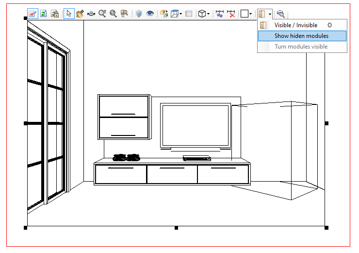
| Visible/invisible: Hides and displays items from the environment on the print page. | Select the item to be hidden/displayed and click the tool button. The Show Invisible Modules option displays, in lines, the modules that are hidden in the environment and also to get an idea of the space occupied by invisible modules, including their position in the project. | |
| Detailing: details the environment modules on the print page by defining scale, cut, view and indicators. | Click on the button and make the necessary settings in the detail window. To insert the information, follow the process for inserting a viewport. |
Move the viewport
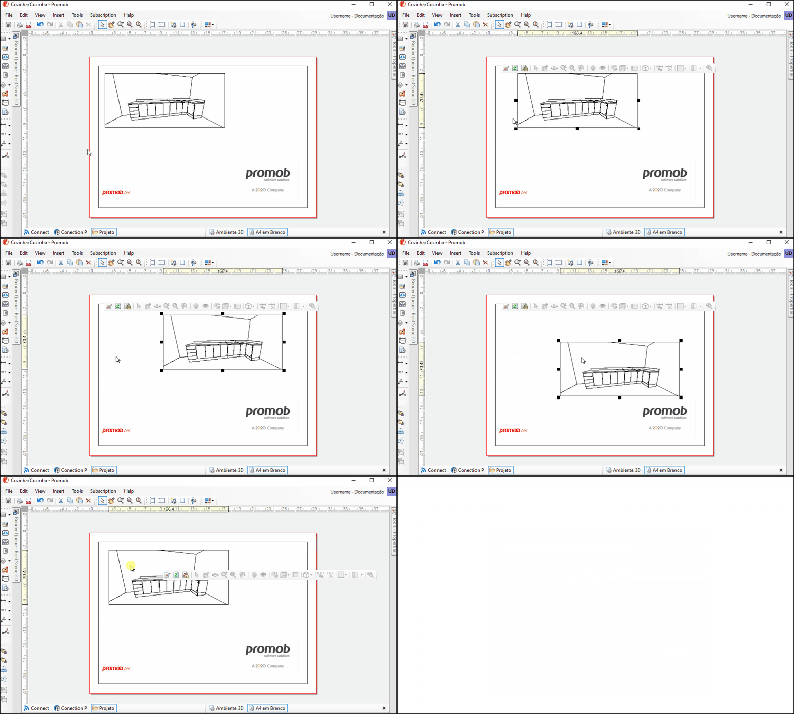
1. Click on the viewport to select it, and drag the mouse to the desired location, or use the arrow keys.
Resize the viewport
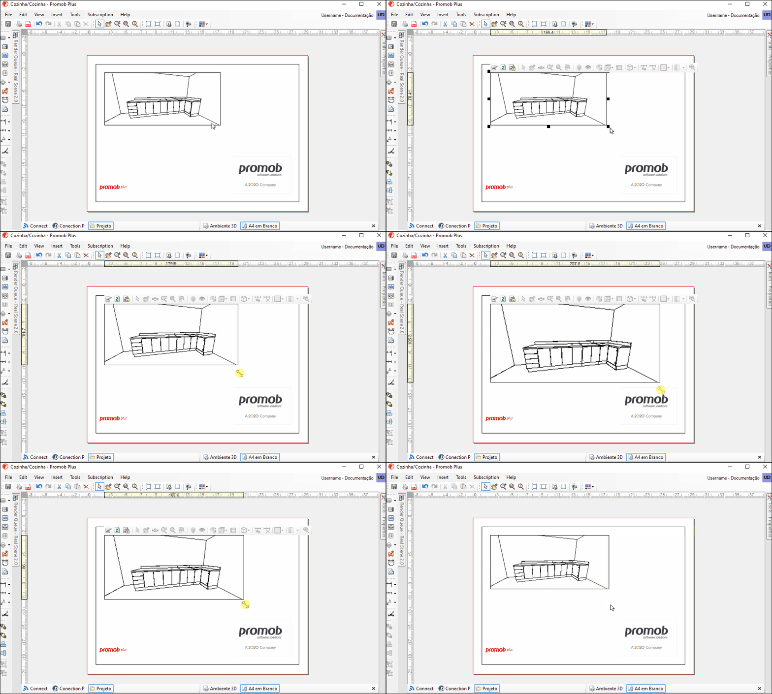
1. Click on the viewport to select it. Click on one of the resize arrows and increase or decrease the size of the viewport as desired.
Rounding the viewport border
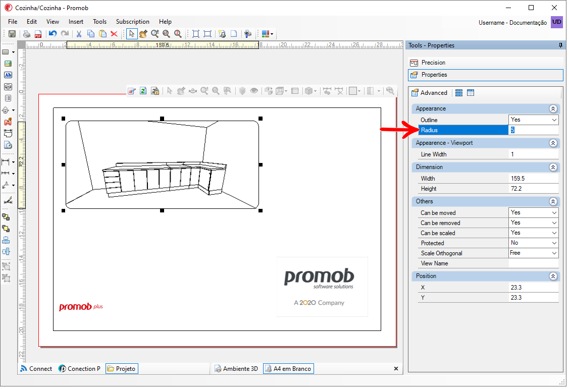
To round the edge of the viewport:
1. Select the viewport and access the Tools Panel - Properties. Change the value of the Radius property.
Hide Viewport Item
A feature that can help the designer to obtain a better visualization of his project is to temporarily make some items invisible (without influencing the budget). With this option it is possible to generate a partial view of your project, displaying only the lower items, or even without the utilities, for example.
IMPORTANT: The floor is the only item in your project that cannot be hidden.
To hide a viewport item:
1. Enable the viewport toolbar, and click the Select button;
2. Click on the item you want to hide. Click the Visible/Invisible button;
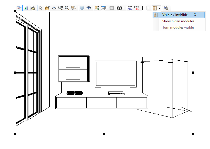
3. The item is hidden in the viewport;
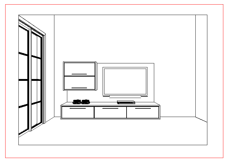
4. Use the Show Hiden Modules option to display in lines the modules that are hidden in the environment, and also to get an idea of the space occupied by invisible modules, including their position in the project.
