The Geometry tool allows the designer to build objects in different ways, such as irregularly shaped tops, recesses, and masonry bases of any shape and dimensions. Before starting the construction of the items, it is necessary to define the construction plan of the geometry, which is the place where the geometry will be created.
To construct geometry:
1. Click on the Geometry button on the top toolbar and select one of the options;

2. Notice that the mouse cursor changes. Before starting the construction of the geometry, right-click on the item you want as a construction plan:

To learn more about building geometry click on one of the options:
1. Free geometry
2. Circular geometry
3. Rectangular geometry
4. Polygonal geometry
5. Build linear geometry
6. Configure properties
1. How to Build Free Geometry
Build free geometry without precision
To build free geometry:
1. Click on the Geometry button and select the Build Geometry option;

2. When the mouse cursor is changed, click with the right mouse button on the plane that you want to construct the geometry;

3. Move the mouse or click to define the second vertex;

4. Repeat the procedure until you create the geometry shape you want;

5. Right-click to finish building the geometry.

Build free geometry with precision
To accurately construct free geometry:
1. Enable the option Build Geometry, define the construction plan of the geometry, position the mouse directing the geometry and type the value of the edge length;
2. Note that the entered value is displayed in Tools - Geometry Building. To define the values for the other properties of the geometry, after informing the length value, press the TAB key to access the other fields:
Length: defines the length of the edge. To determine the length, just enter the value at the time of construction of the geometry;
Angle: defines the angle of the edge; After determining the length of the edge, it is possible to determine the angle or direction of the edge;
Height: defines the height of the geometry. By default, the height of the geometry always starts at 150 mm. The height can be changed after its construction through the properties;
Spacing: defines the spacing of the geometry in relation to its plane;
Offset: thickness of the geometry construction line;
Incr. Linear: added value to the segment when constructing the geometry with the drag of the mouse;
Incr. Angular: angle value when moving the mouse in the design;
Use values as default: saves the values of height and increments to be used in the construction of other geometries of the same type;
Drill: if this option is enabled, circular geometry perforates your construction plan.
IMPORTANT: the Length and Angle properties can be set only during construction of the geometry.

3. Right-click to finish building the geometry.
2. How to Build Circular Geometry
Build circular geometry without precision
To construct a circular geometry:
1. Click on the Geometry button and select the Build Circular Geometry option;

2. When the mouse cursor is changed, click with the right mouse button on the plane that you want to construct the geometry;
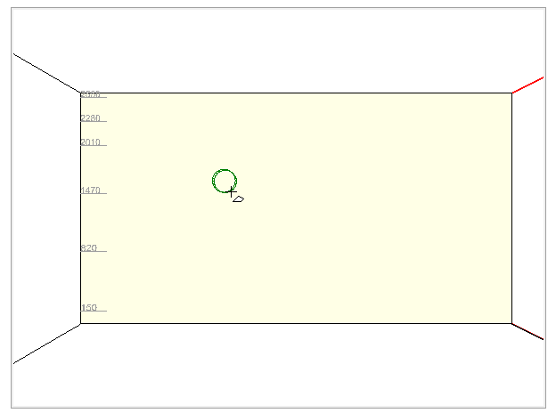
3. O local clicado no plano de construção é o centro do círculo. Mova o mouse para definir o raio do círculo;
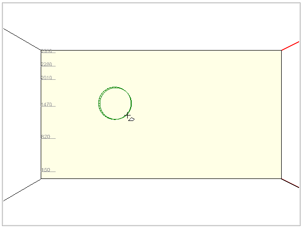
4. Click with the mouse to finish building the circular geometry.
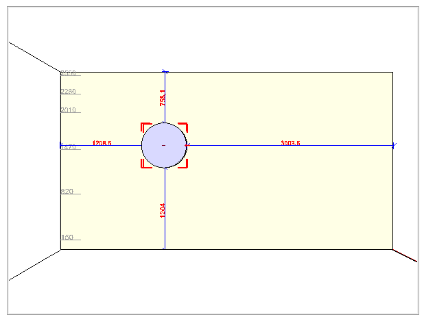
Build circular geometry with precision
To accurately construct circular geometry:
1. Enable the option Build Circular Geometry, define the construction plan of the geometry, position the mouse directing the geometry and enter the radius value;
2. Note that the entered value is displayed in the Tools - Build Circular Geometry. To define the values for the other properties of the geometry, after informing the Radius value, press the TAB key to access the other fields:
Radius: defines the radius of the circumference;
Base Angle: defines the position of the circumference where the construction of the geometry starts;
Arc Angle: angle of the arc of the circumference;
Height: defines the height of the geometry. By default, the height of the geometry is always started at 150mm;
Drill: determines whether or not the constructed geometry will pierce the plane on which it is being built;

3. After entering the values for the geometry properties, press Enter to view the geometry.
3. How to Build Rectangular Geometry
Build rectangular geometry without precision
To construct a rectangular geometry without precision:
1. Click on the Geometry button and select the Build Rectangular Geometry option;

2. When the mouse cursor is changed, click with the right mouse button on the plane that you want to construct the geometry;
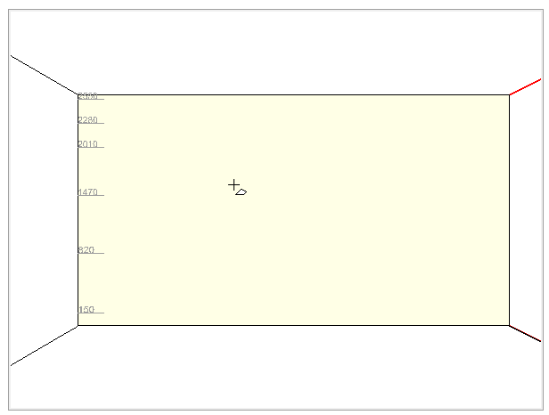
3. Move the mouse diagonally to determine the size of the geometry;
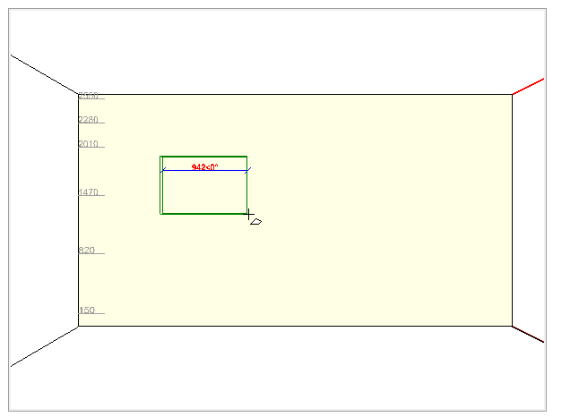
4. Click with the mouse to finish the construction of the geometry.
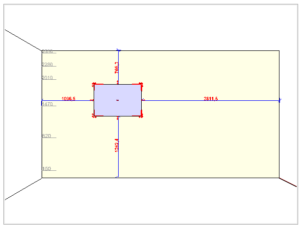
Accurately build rectangular geometry
To accurately construct rectangular geometry:
1. Enable the option Build Rectangular Geometry, define the construction plan of the geometry, position the mouse directing the geometry and enter the geometry width value;
2. Notice that the entered value is displayed in the Tools - Build Rectangular Geometry. To define the values for the other properties of the geometry, after informing the width, press the TAB key to access the other fields:
Width: defines the width of the rectangle;
Depth: defines the depth of the rectangle;
Height: defines the height of the rectangle. By default, the height of the geometry is always started at 150mm;
Spacing: defines the spacing of the geometry with respect to the plane on which it is being built;
Drill: determines whether or not the constructed geometry will pierce the plane on which it is being built;
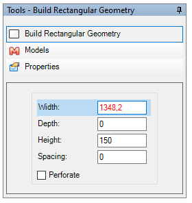
3. After entering the values for the geometry properties, press Enter to view the geometry.
4. How to Build Polygonal Geometry
Build polygonal geometry without precision
To construct polygonal geometry without precision:
1. Click on the Geometry button and select the Build Polygonal Geometry option;
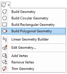
2. When the mouse cursor is changed, click with the right mouse button on the plane that you want to construct the geometry;
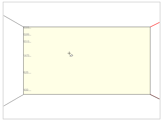
3. The location clicked on the building plan is the center of the polygon. Move the mouse to define the size of the geometry;
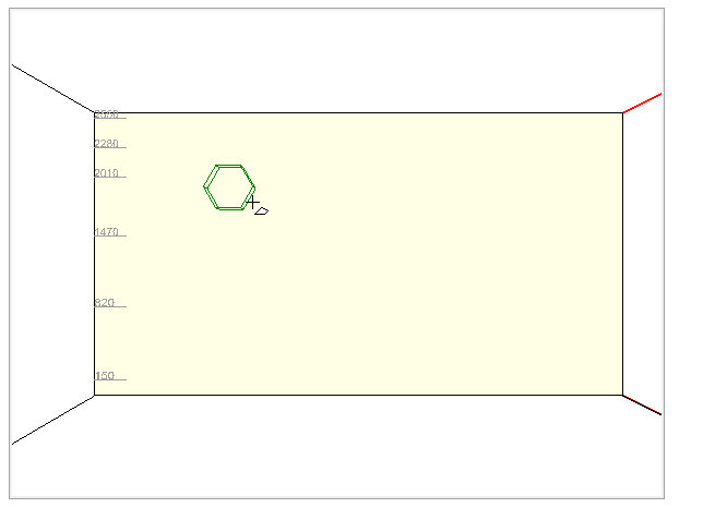
4. Click with the mouse to finish the construction of the polygonal geometry.
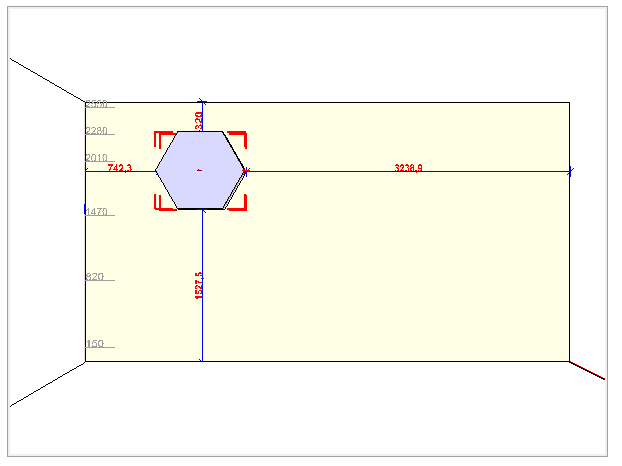
Accurately build polygonal geometry
To accurately construct a polygonal geometry:
1. Enable the option Construct Polygonal Geometry, define the construction plan of the geometry, position the mouse directing the geometry and type the number of sides of the geometry;
2. Notice that the entered value is displayed in the Tools - Build Geometry. To define the values for the other properties of the geometry, after informing the number of sides, press the TAB key to access the other fields:
Inscribed Radius: defines the value of the polygon's internal radius;
Circumscribed Radius: defines the value of the external radius of the polygon;
Side Size: defines the dimension of each side (corresponds to the Circumscribed Radius);
Height: defines the height of the rectangle. By default, the height of the geometry is always started at 150mm;
Drill: determines whether or not the constructed geometry will pierce the plane on which it is being built;

3. After entering the values for the geometry properties, press Enter to view the geometry.
5. How to Build Linear Geometry
Build linear geometry without precision
To construct linear geometry without precision:
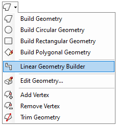
1. Click on the Geometry button and select the option Linear Geometry Builder;
2. When the mouse cursor is changed, click on the plane you want to construct the geometry;

3. Move the mouse cursor to direct the construction and click to form the first segment;

4. Repeat the same procedure to build the remaining segments;

5. Right-click to finish the construction;
6. In the window that appears, make the necessary settings for the geometry:
Finalize construction: the geometry is finished and inserted in the 3D space as it was built;
Edit profile: opens the Geometry Editor Profile Editor;
Convert to modulation item: displays the options for items and models for converting linear geometry. These items are available on the Promob modulation bar and thus become part of the design budget;
Color and Material: displays color and material options that can be applied to the geometry;
Create Segments: this option divides the geometry so that each segment can be treated individually in 3D space;
Alignment: determines the alignment of the geometry in the design according to the points selected during its construction. The alignment options are: top, bottom, front, back;

7. Click OK to view the geometry in the design.

Accurately build linear geometry
To accurately construct linear geometry:
1. Enable the option Construct Linear, define the construction plan of the geometry, position the mouse directing the geometry and type the value of the edge length;
2. Notice that the entered value is displayed in the Tools - Linear Geometry Build. To define the values for the other properties of the geometry, after informing the number of sides, press the TAB key to access the other fields:
Length: defines the length of the edge. To determine the length, just enter the value at the time of construction of the geometry;
Angle: defines the angle of the edge; After determining the length of the edge, it is possible to determine the angle or direction of the edge;
Height: defines the height of the geometry. By default, the height of the geometry always starts at 150 mm. The height can be changed after its construction through the properties;
Spacing: defines the spacing of the geometry in relation to its plane;
Thickness: thickness of the geometry construction line;
Incr. Linear: added value to the segment when constructing the geometry with the drag of the mouse;
Incr. Angular: angle value when moving the mouse in the design;
Orientation: indicates the side of the geometry that will receive the value informed in the length field;
Use values as default: saves the values of height and increments to be used in the construction of other geometries of the same type;

3. After entering the values for the geometry properties, press Enter to view the geometry.
6. Setting Geometry Properties
To configure the geometry properties:
Free geometry properties
Circular geometry properties
Rectangular geometry properties
Polygonal geometry properties
Free geometry properties
The properties of free geometry are:
1. Selected Border:
Apply Profile: defines whether or not the profile will be applied to the selected border;
Length: displays the length of the selected border;
Arrow: defines the curvature of the selected border;
2. Quotas:
Distance: distance from geometry in relation to the plane on which it was built;
Previous dimension: available distance to the left of the geometry;
Posterior dimension: available distance to the right of the geometry;
Lower dimension: available distance below the geometry;
Upper dimension: available distance above the geometry;
3. Drawing:
Draw Bottom Face: defines whether the bottom face of the geometry will be drawn or not;
Draw Top Face: defines whether the top face of the geometry will be drawn or not;
Draw Profile: defines whether the profile (sides) of the geometry will be drawn or not;
Directly selectable: if the value is equal to Yes, when clicking on an aggregate the parent is selected. If the value is equal to No, the aggregate is selected;
4. Dimensions:
Width: defines the width of the geometry;
Height: defines the height of the geometry;
Depth: defines the depth of the geometry;
Scalar: defines whether the geometry proportion will be maintained or not when its dimensions are changed;
Area: displays the area of the selected face of the geometry;
5. Material:
Map by Region: defines whether the material applied in the geometry starts to be mapped by the geometry profile or region;
6. Budget:
Budgeted: defines whether or not the geometry will be budgeted;
Description: inform the description for the geometry that will be displayed in the budget;
Category: inform the category for the geometry that will be displayed in the budget;
Group: inform the group of the geometry;
Reference: inform the reference for the geometry that will be displayed in the budget;
Price: inform the price of the geometry;
7. Others:
Layer: defines the geometry layer;
Make Shadow: defines whether or not the geometry shadows in the Presentation fill mode;
Movable: defines whether the geometry can be moved or not;
Observations: when clicking on the Details button, the text window to enter the observation is displayed;
Visible: defines whether or not the geometry can be displayed in the design;
8. Piercing:
Drill: defines whether or not the geometry can pierce its insertion plane;
Depth: defines the depth of the hole;
9. Absolute Position:
X: defines the position of the geometry on the X axis of the design;
Y: defines the position of the geometry on the Y axis of the design;
Z: defines the position of the geometry on the Z axis of the design;
Rotation: defines the rotation of the geometry in the design;
10. Relative Position:
X: defines the position of the geometry on the X axis of the plane where it was built;
Y: defines the position of the geometry on the Y axis of the plane where it was built;
Z: defines the position of the geometry on the Z axis of the plane where it was built;
Circular geometry properties
The properties of circular geometry are:
1. Angles:
Arc Angle: angle of the arc of the circumference;
Base Angle: defines the position of the circumference where the construction of the geometry starts;
2. Selected Border:
Apply Profile: defines whether or not the profile will be applied to the selected border;
Length: displays the length of the selected border;
Arrow: defines the curvature of the selected border;
3. Quotas:
Distance: distance from geometry in relation to the plane on which it was built;
Previous dimension: available distance to the left of the geometry;
Posterior dimension: available distance to the right of the geometry;
Lower dimension: available distance below the geometry;
Upper dimension: available distance above the geometry;
4. Drawing:
Draw Bottom Face: defines whether the bottom face of the geometry will be drawn or not;
Draw Top Face: defines whether the top face of the geometry will be drawn or not;
Draw Profile: defines whether the profile (sides) of the geometry will be drawn or not;
Directly selectable: if the value is equal to Yes, when clicking on an aggregate the parent is selected. If the value is equal to No, the aggregate is selected;
5. Dimensions:
Width: defines the width of the geometry;
Depth: defines the depth of the geometry;
Height: defines the height of the geometry;
Radius: defines the radius of the geometry;
Scalar: defines whether the geometry proportion will be maintained or not when its dimensions are changed;
Area: displays the area of the selected face of the geometry;
6. Material:
Map by Region: defines whether the material applied to the geometry starts to be mapped by the geometry profile or region;
7. Budget:
Budgeted: defines whether or not the geometry will be budgeted;
Description: inform the description for the geometry that will be displayed in the budget;
Category: inform the category for the geometry that will be displayed in the budget;
Group: inform the group of the geometry;
Reference: inform the reference for the geometry that will be displayed in the budget;
Price: inform the price of the geometry;
8. Others:
Layer: defines the geometry layer;
Make Shadow: defines whether or not the geometry shadows in the Presentation fill mode;
Movable: defines whether the geometry can be moved or not;
Observations: when clicking on the Details button, the text window to enter the observation is displayed;
Visible: defines whether or not the geometry can be displayed in the space;
9. Piercing:
Drill: defines whether or not the geometry can pierce its insertion plane;
Depth: defines the depth of the hole;
10. Absolute Position:
X: defines the position of the geometry on the X axis of the design;
Y: defines the position of the geometry on the Y axis of the design;
Z: defines the position of the geometry on the Z axis of the design;
Rotation: defines the rotation of the geometry in the design;
11. Relative Position:
X: defines the position of the geometry on the X axis of the plane where it was built;
Y: defines the position of the geometry on the Y axis of the plane where it was built;
Z: defines the position of the geometry on the Z axis of the plane where it was built.
Rectangular geometry properties
The properties of rectangular geometry are:
1. Selected Border:
Apply Profile: defines whether or not the profile will be applied to the selected border;
Length: displays the length of the selected border;
Arrow: defines the curvature of the selected border;
2. Quotas:
Distance: distance from geometry in relation to the plane on which it was built;
Previous dimension: available distance to the left of the geometry;
Posterior dimension: available distance to the right of the geometry;
Lower dimension: available distance below the geometry;
Upper dimension: available distance above the geometry;
3. Drawing:
Draw Bottom Face: defines whether the bottom face of the geometry will be drawn or not;
Draw Top Face: defines whether the top face of the geometry will be drawn or not;
Draw Profile: defines whether the profile (sides) of the geometry will be drawn or not;
Directly selectable: if the value is equal to Yes, when clicking on an aggregate the parent is selected. If the value is equal to No, the aggregate is selected;
4. Dimensions:
Width: defines the width of the geometry;
Height: defines the height of the geometry;
Depth: defines the depth of the geometry;
Scalar: defines whether the geometry proportion will be maintained or not when its dimensions are changed;
Area: displays the area of the selected face of the geometry;
5. Material:
Map by Region: defines whether the material applied in the geometry starts to be mapped by the geometry profile or region;
6. Budget:
Budgeted: defines whether or not the geometry will be budgeted;
Description: inform the description for the geometry that will be displayed in the budget;
Category: inform the category for the geometry that will be displayed in the budget;
Group: inform the group for the geometry;
Reference: inform the reference for the geometry that will be displayed in the budget;
Price: inform the price of the geometry;
7. Others:
Layer: defines the geometry layer;
Make Shadow: defines whether or not the geometry shadows in the Presentation fill mode;
Movable: defines whether the geometry can be moved or not;
Observations: when clicking on the Details button, the text window to enter the observation is displayed;
Visible: defines whether or not the geometry can be displayed in the design;
8. Piercing:
Drill: defines whether or not the geometry can pierce its insertion plane;
Depth: defines the depth of the hole;
9. Absolute Position:
X: defines the position of the geometry on the X axis of the design;
Y: defines the position of the geometry on the Y axis of the design;
Z: defines the position of the geometry on the Z axis of the design;
Rotation: defines the rotation of the geometry in the design;
10. Relative Position:
X: defines the position of the geometry on the X axis of the plane where it was built;
Y: defines the position of the geometry on the Y axis of the plane where it was built;
Z: defines the position of the geometry on the Z axis of the plane where it was built.
Polygonal geometry properties
The properties of polygonal geometry are:
1. Selected Border:
Apply Profile: defines whether or not the profile will be applied to the selected border;
Length: displays the length of the selected border;
Arrow: defines the curvature of the selected border;
2. Quotas:
Distance: distance from geometry in relation to the plane on which it was built;
Previous dimension: available distance to the left of the geometry;
Posterior dimension: available distance to the right of the geometry;
Lower dimension: available distance below the geometry;
Upper dimension: available distance above the geometry;
3. Drawing:
Draw Bottom Face: defines whether the bottom face of the geometry will be drawn or not;
Draw Top Face: defines whether the top face of the geometry will be drawn or not;
Draw Profile: defines whether the profile (sides) of the geometry will be drawn or not;
Directly selectable: if the value is equal to Yes, when clicking on an aggregate the parent is selected. If the value is equal to No, the aggregate is selected;
4. Dimensions:
Height: defines the height of the geometry;
Sides: defines the number of sides of the geometry;
Circumscribed Radius: defines the value of the external radius of the polygon;
Inscribed Radius: defines the value of the polygon's internal radius;
Side Size: defines the dimension of each side of the geometry;
Area: displays the area of the selected face of the geometry;
5. Material:
Map by Region: defines whether the material applied in the geometry starts to be mapped by the geometry profile or region;
6. Budget:
Budgeted: defines whether or not the geometry will be budgeted;
Description: inform the description for the geometry that will be displayed in the budget;
Category: inform the category for the geometry that will be displayed in the budget;
Group: inform the group for the geometry;
Reference: inform the reference for the geometry that will be displayed in the budget;
Price: inform the price of the geometry;
7. Others:
Layer: defines the geometry layer;
Make Shadow: defines whether or not the geometry shadows in the Presentation fill mode;
Movable: defines whether the geometry can be moved or not;
Observations: when clicking on the Details button, the text window to enter the observation is displayed;
Visible: defines whether or not the geometry can be displayed in the design;
8. Piercing:
Drill: defines whether or not the geometry can pierce its insertion plane;
Depth: defines the depth of the hole;
9. Absolute Position:
X: defines the position of the geometry on the X axis of the design;
Y: defines the position of the geometry on the Y axis of the design;
Z: defines the position of the geometry on the Z axis of the design;
Rotation: defines the rotation of the geometry in the design;
10. Relative Position:
X: defines the position of the geometry on the X axis of the plane where it was built;
Y: defines the position of the geometry on the Y axis of the plane where it was built;
Z: defines the position of the geometry on the Z axis of the plane where it was built.