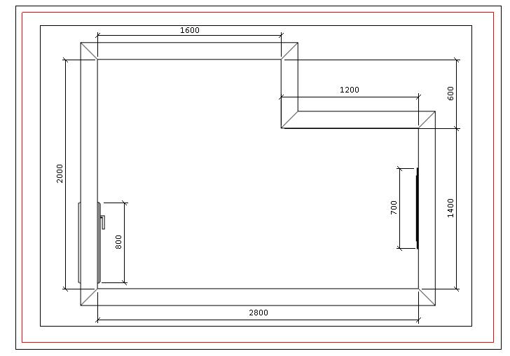
The information regarding dimensions and distances between the various items can be of great importance to simplify the work of assembling the design.
The designer can, in addition to consulting any of this information, insert lines and dimensions in the drawing that will allow a simplified later consultation either on the computer screen or in printed material.
Promob offers a set of tools that allow you to quickly and practically clarify any question related to the dimension of items, as well as the distance between them in the design.
With Dimensions, it is possible to mark the points that limit a piece of furniture, a design or a wall, specifying its value in it. The information regarding dimensions and distances between the various items can be of great importance to simplify the work of assembling the design.
Dimension types
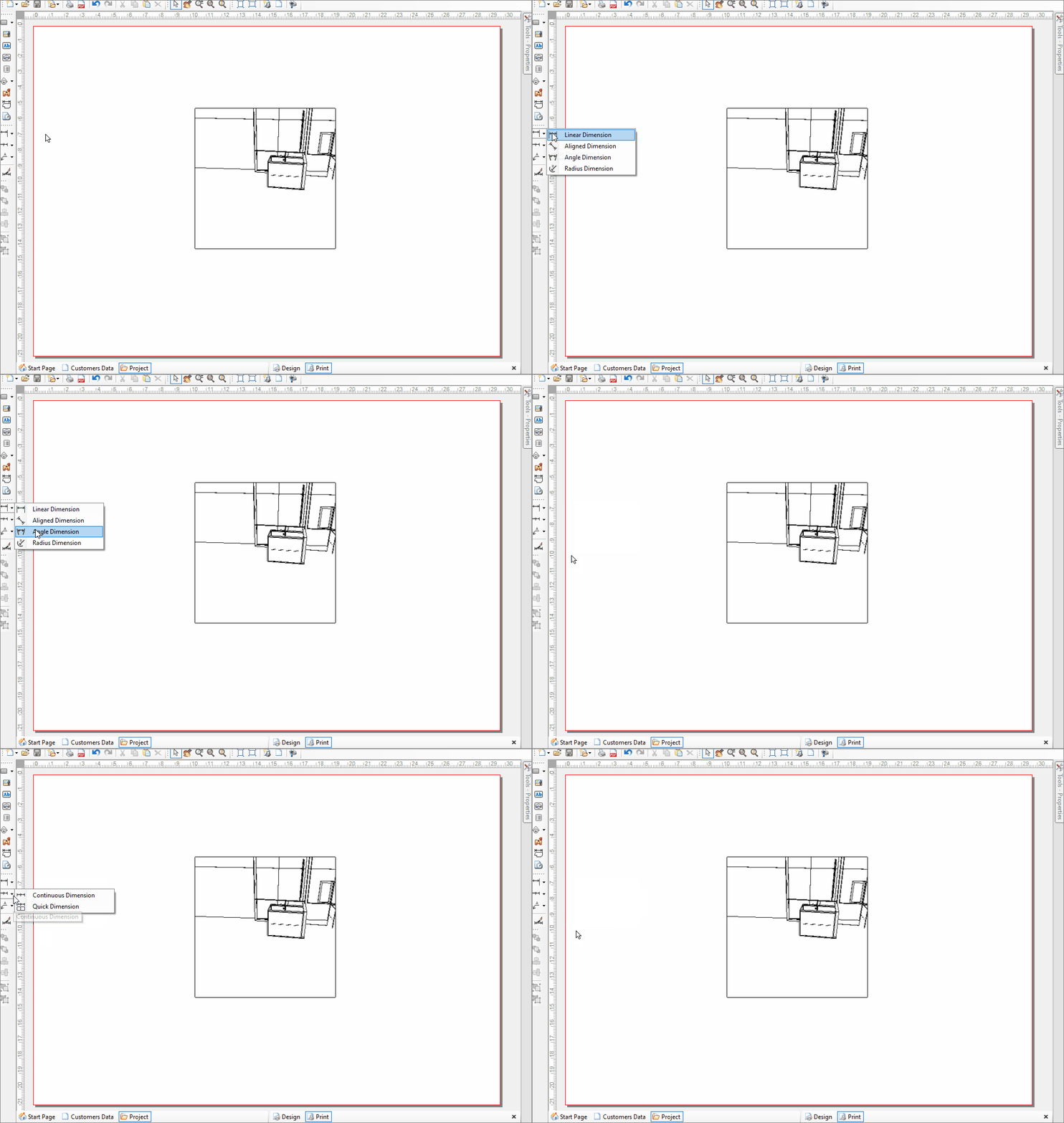
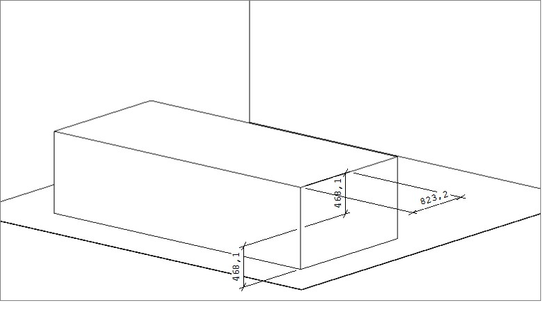
The dimensions are available on the print page, and there are six options: Linear, Aligned, Angular, Straight, Continuous and Fast.
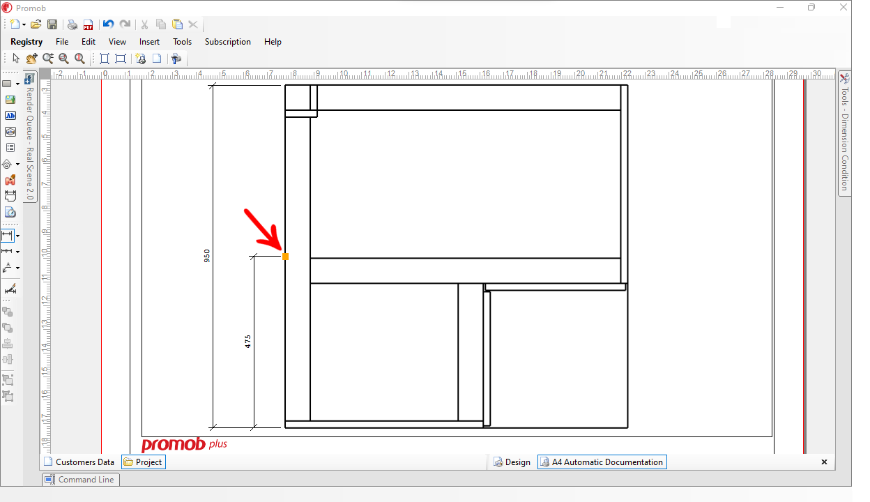
IMPORTANT: Starting with Promob version 5.60.16.77, when you position the mouse near the center of the dimension, an orange square appears at the midpoint of the edge, so that you can add a new dimension with precision.
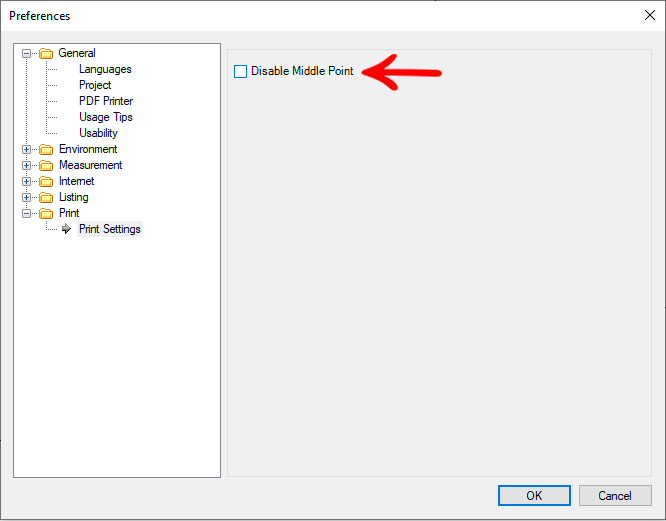
From version 5.60.17.11 of Promob is possible to disable the middle point of the quota, in the print list via the menu Preferences.
To disable the middle point:
1. With Promob open, access Tools - Preferences - Print - Print Settings.
2. Enable or disable the optionDisable Middle Point as required.
- Linear dimension: dimension the distance between two points. To insert it, perform the procedures below:
- Insert a viewport on the print page.
- Position the design in the desired view, and in orthogonal mode.
- Select Viewport and go to Edit Viewport.
- In Views, select one of the options to view your design.
- Select Orthogonal / Perspective.
- In the left sidebar, select the Linear Dimension.
- Click on the first point, move the mouse and click on the second point that you want to end the dimension.
- Move the mouse left / right or up / down to position the dimension and click to insert it.
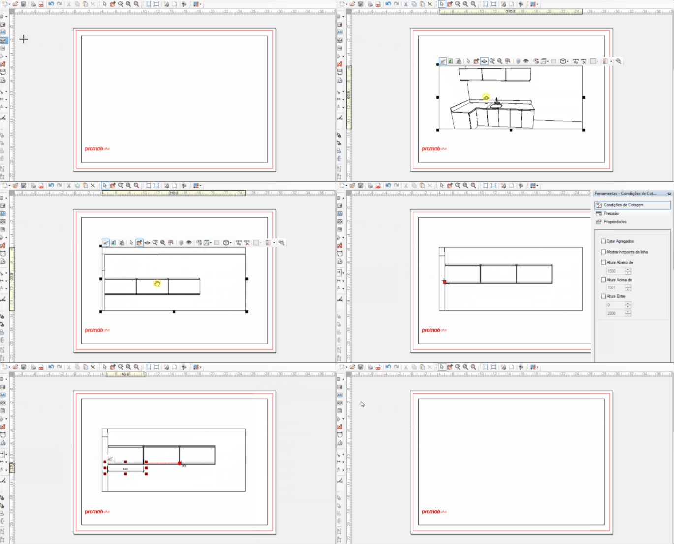
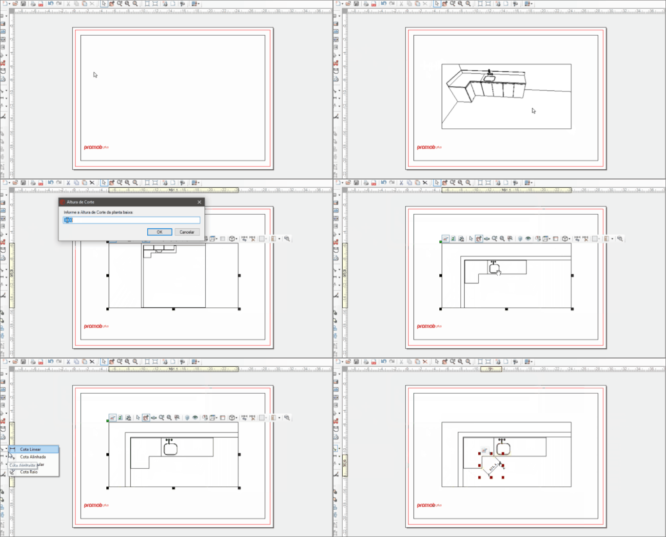
- Aligned dimension: dimension the diagonal distance between two points.
- Insert a viewport on the print page.
- Position the design in the desired view, and in orthogonal mode.
- Select Viewport and go to Edit Viewport.
- In Views, select one of the options to view your design.
- Select Orthogonal / Perspective.
- In the left sidebar, select the Aligned Dimension.
- Click on the first point, move the mouse and click on the second point that you want to end the dimension.
- Move the mouse left / right or up / down to position the dimension and click to insert it.
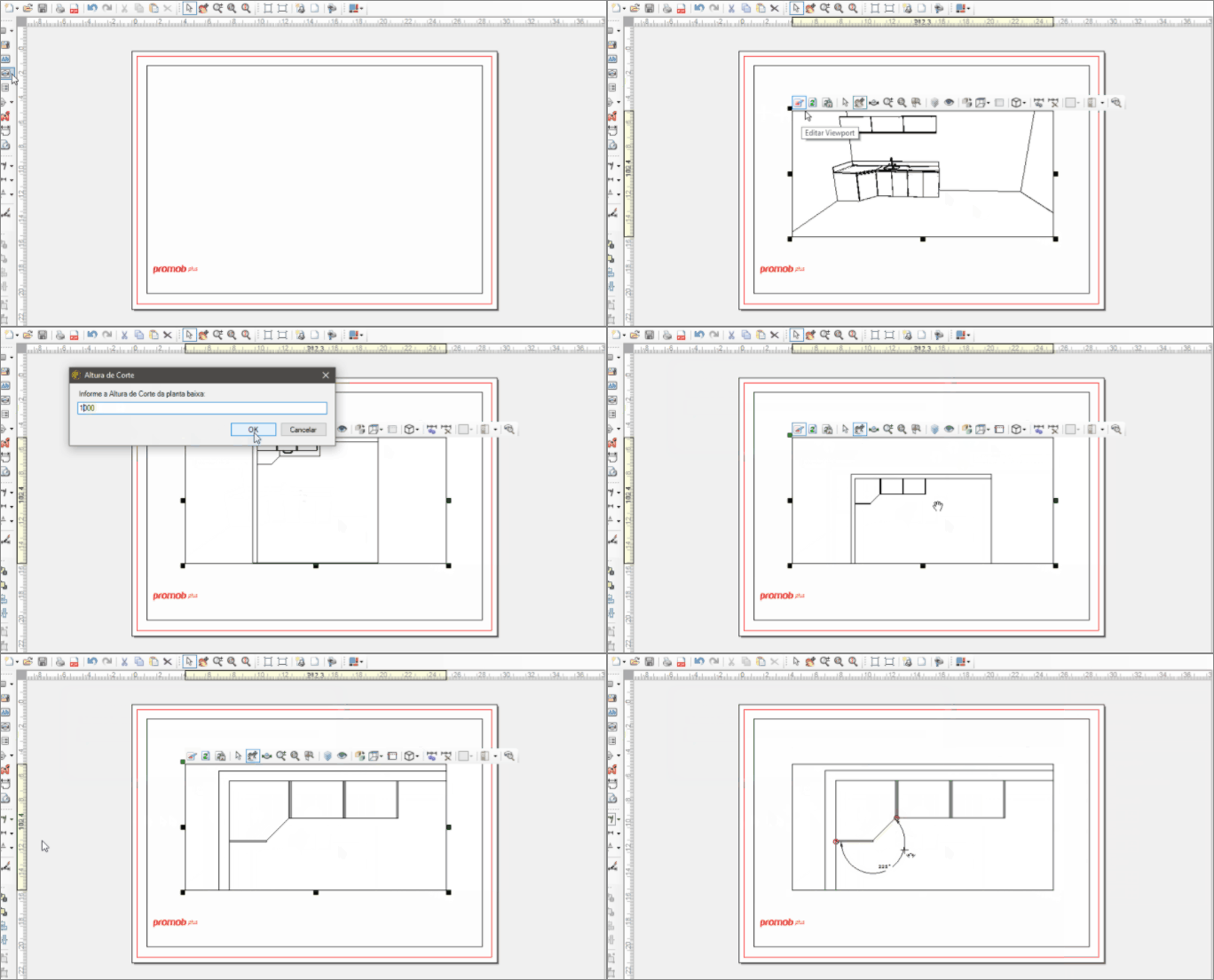
- Angular dimension: dimension an angle.
- Insert a viewport on the print page.
- Position the design in the desired view, and in orthogonal mode.
- Select Viewport and go to Edit Viewport.
- In Views, select one of the options to view your design.
- Select Orthogonal / Perspective.
- In the left sidebar, select the Angular Dimension.
- Move the mouse left / right or up / down to position the dimension and click to insert it.
IMPORTANT: the angular dimension requires the indication of at least three points to determine the dimension, since without them it is not possible to identify the points to be dimensioned. Click on the three points and notice that the second point indicates the location of the angle to be dimensioned.
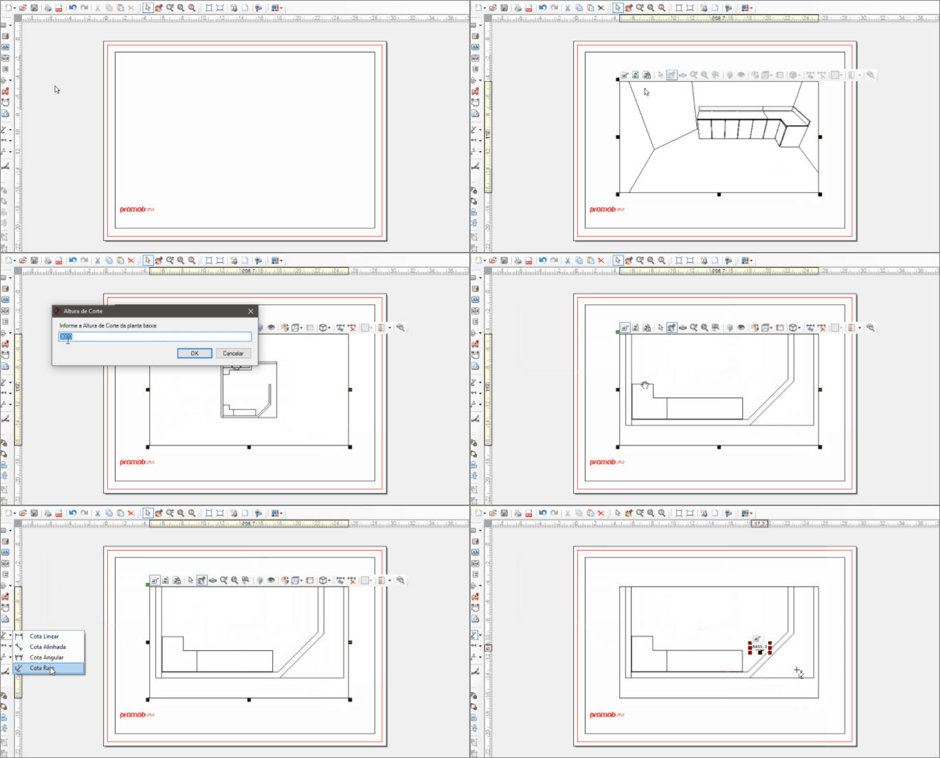
- Dimension Radius: dimension the radius of a circle.
- Insert a viewport on the print page.
- Position the design in the desired view, and in orthogonal mode.
- Select Viewport and go to Edit Viewport.
- In Views, select one of the options to view your design.
- Select Orthogonal/Perspective.
- In the left sidebar, select the Radius dimension
- Click on the center point of the circle and then on one of the hotpoints available on the arc;
- Move the mouse left/right or up/down to position the dimension and click to insert it.
IMPORTANT: the radius dimension needs the indication of two points.
- Quick Dimension: lists several items at the same time.
- Insert a viewport on the print page.
- Position the design in the desired view, and in orthogonal mode.
- Select Viewport and go to Edit Viewport.
- In Views, select one of the options to view your design.
- Select Orthogonal / Perspective.
- In the left sidebar, select Quick Dimension.
- Through clicks, open a selection window on the objects you want to quote, after dragging vertically or horizontally, according to your need.
- Click with the mouse to place the dimension.
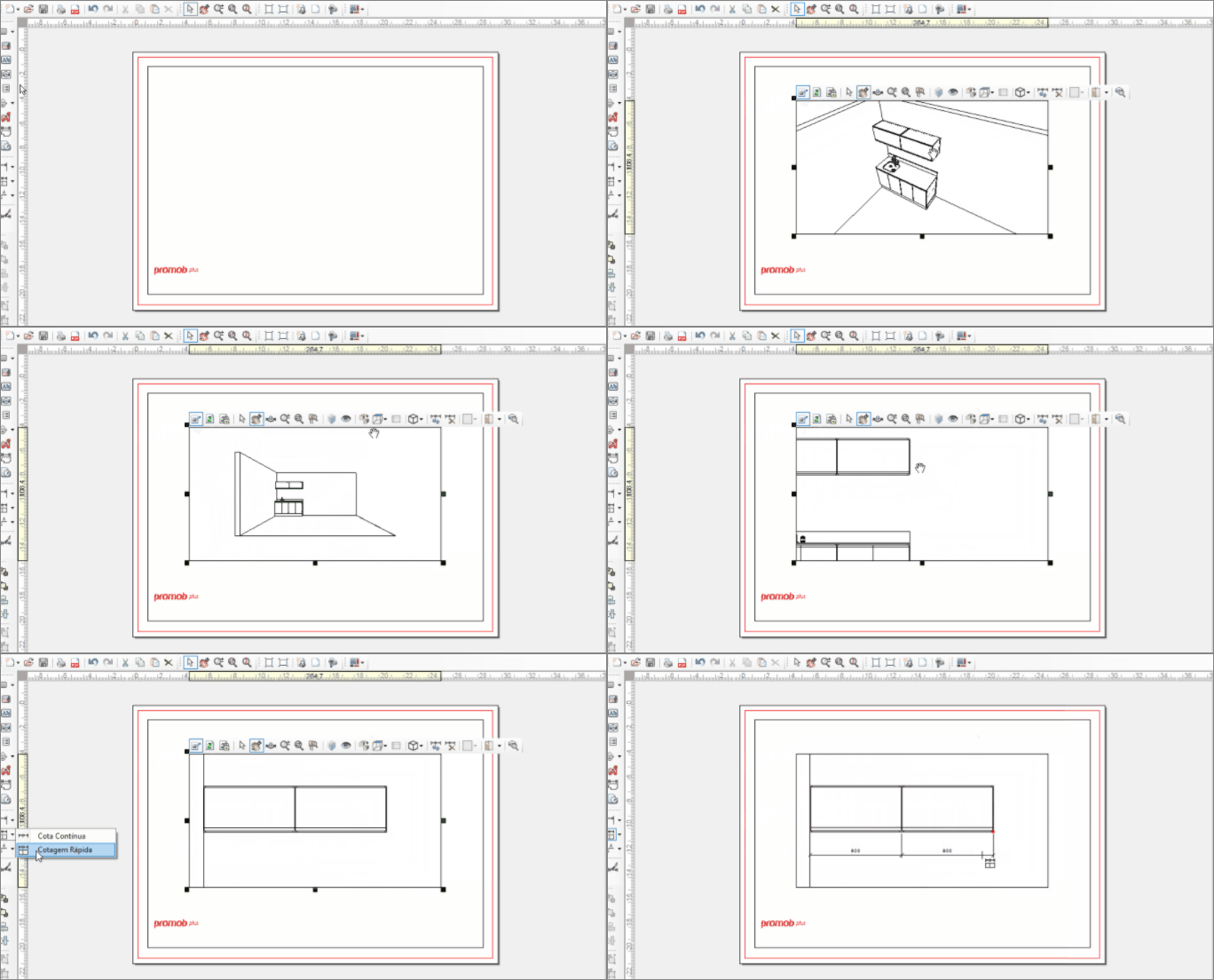
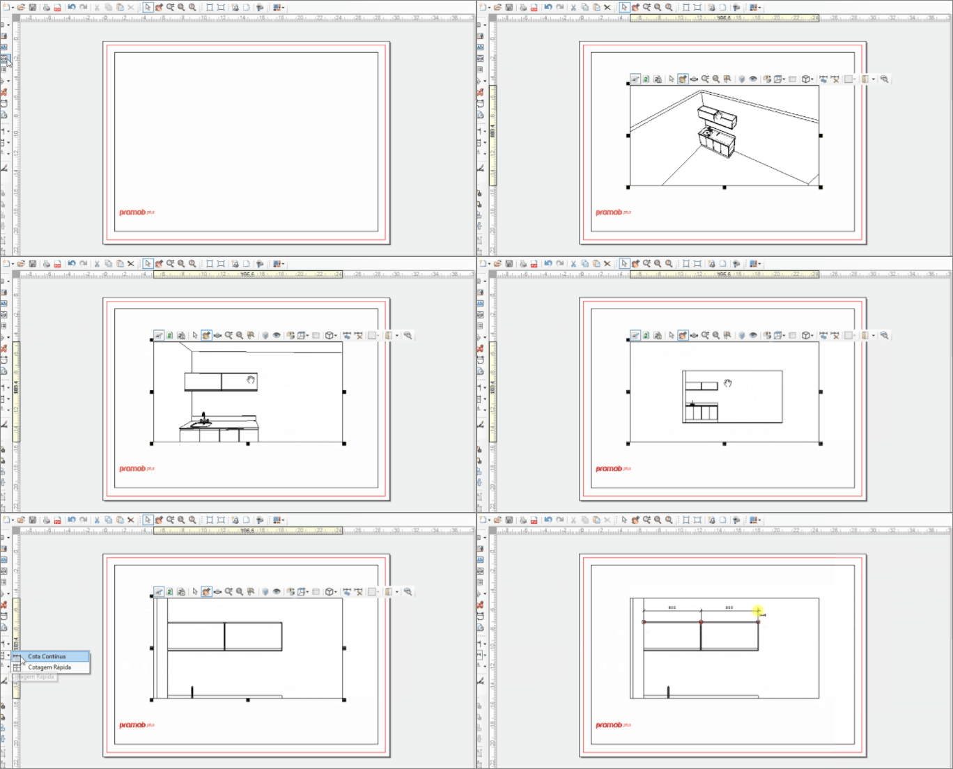
- Continuous dimension: dimension the distance between several modules at the same time.
- Insert a viewport on the print page.
- Position the design in the desired view, and in orthogonal mode.
- Select Viewport and go to Edit Viewport.
- In Views, select one of the options to view your design.
- Select Orthogonal/Perspective.
- In the left sidebar, select the Continuous Dimension.
- Click on the points you want to quote. After the last point, click with the right mouse button to finish the dimensioning.
- With the left mouse button, fix the position of the dimensions. Move the mouse left / right or up / down to position the dimension.
Remove Dimension
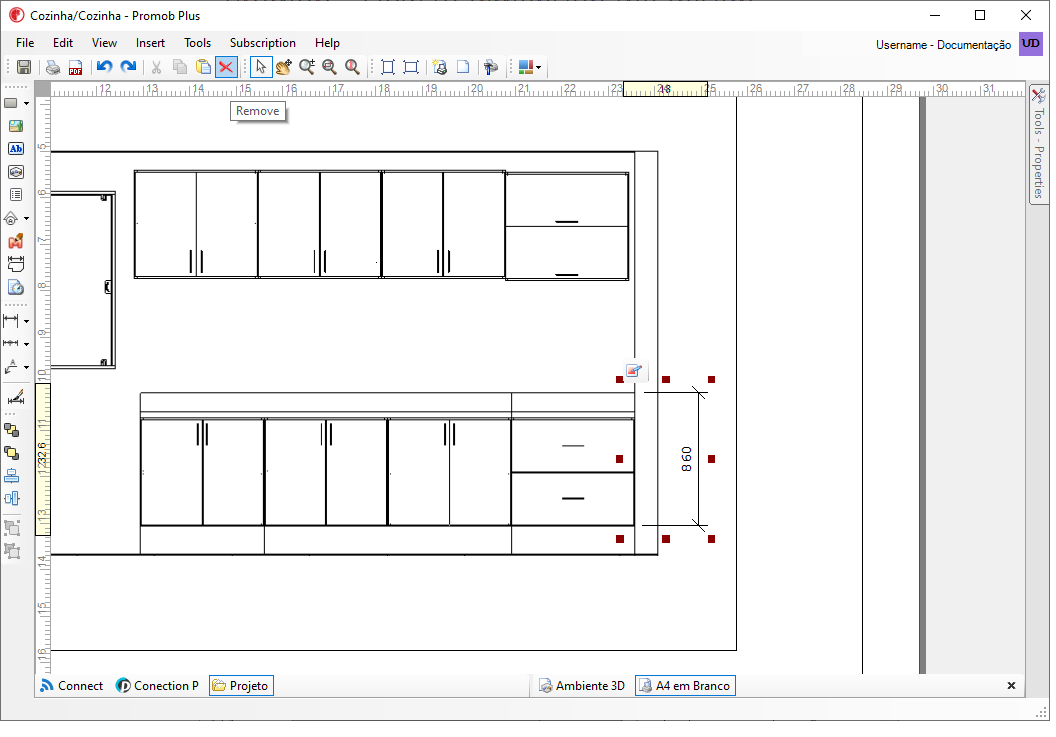
To delete only one dimension from the viewport, there are two options:
Option 1: Select the dimension you want to delete, and press Remove on the keyboard.
Option 2: Select the dimension you want to delete, and select Remove on the top bar.
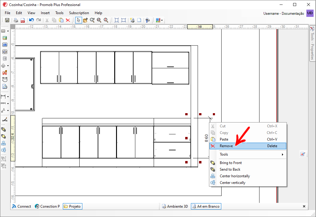
Option 3: Select the dimension with the right mouse button and select Remove.
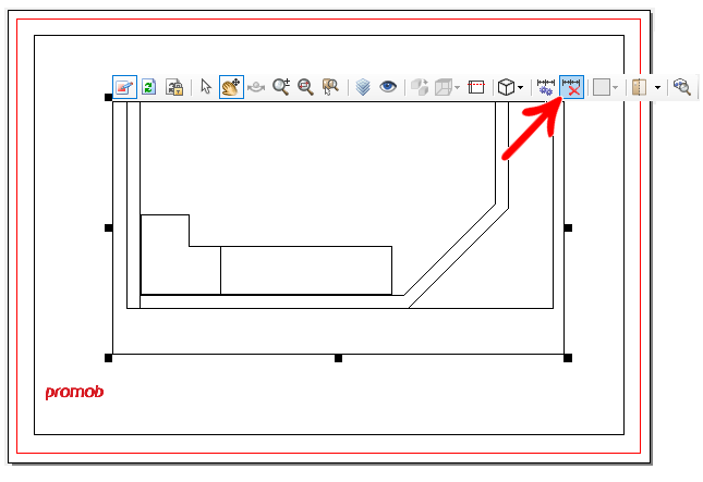
To delete all dimensions from the viewport, do the following:
1. Select the viewport, and click Edit Viewport. Then select Remove all dimensions.
Edit the of the dimension value
To edit the value of the dimensions:
1. In the print area viewport, double-click with the mouse on the dimension you want to edit;
2. The current dimension value is displayed in the open window. Enter the information you want to display and click OK;

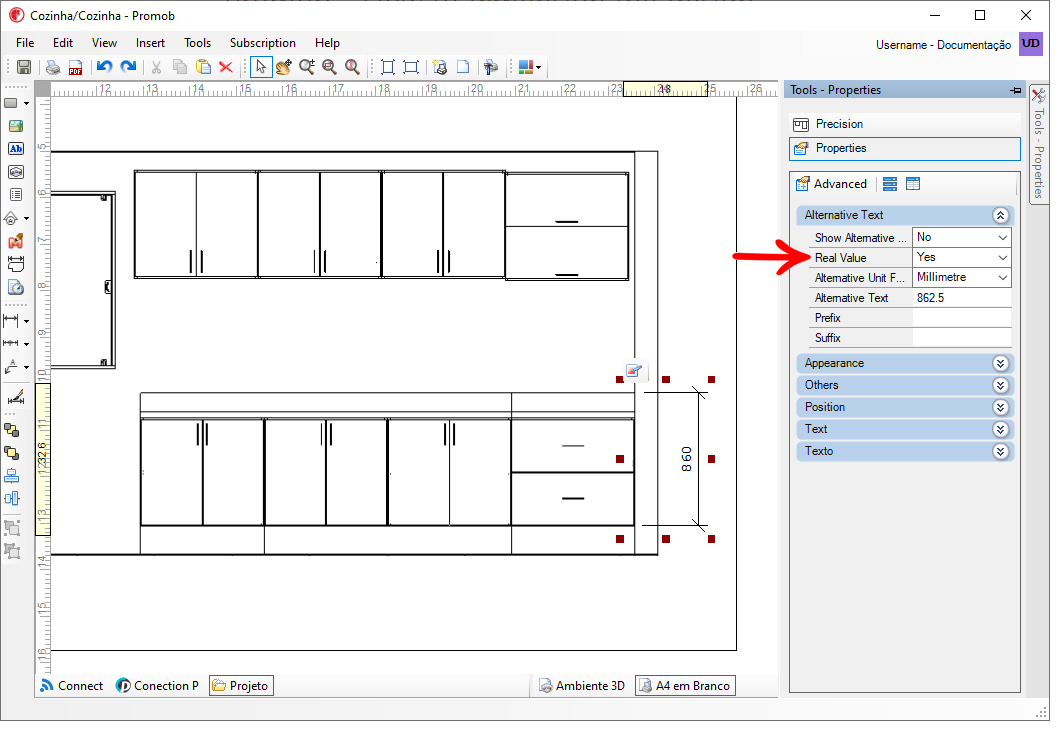
3. To display the real value of the dimension again, access the Tools - Properties with the dimension selected and in the Text category, change the Real Value property to Yes.
Dimension Properties
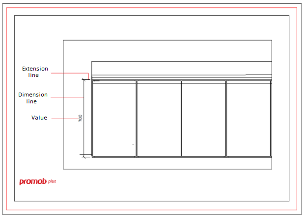
The dimension object consists of two leader lines, the dimension line and the value:
To configure the properties of the dimensions, perform the procedures below:
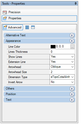
1. Select the dimension to be edited, and access Tools - Properties:
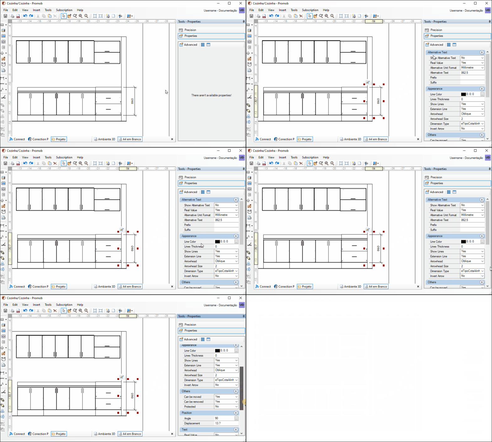
2. In Appearance, set:
- Line color: defines the color that the dimension line and the leader lines will be displayed;
- Line thickness: defines the thickness of the dimension line and the leader lines;
- Show Lines: defines whether or not lines are displayed.
- Extension line: determines whether extension lines are drawn for the dimension or not;
- Arrowhead: defines the arrow model to be used at the end of the dimension line;
- Arrowhead Size: defines the size of the arrow;
- Dimension Type: changes the dimension type from normal and Leader type
- Invert arrow: defines whether the arrowhead, defined in the item Size Arrow, will be inverted or not;
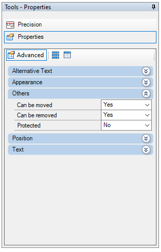
3. In Others, define:
- Can be moved: define whether the dimension can be moved or not;
- Can be removed: define whether the dimension can be removed or not;
- Protected: define whether the dimension can change or not;
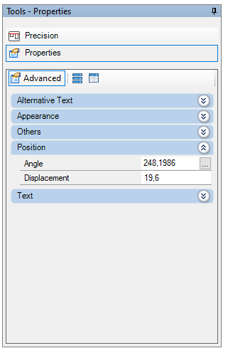
4. In Position, define:
- Angle: set the dimension of the dimension;
- Displacement: define the distance between the points used in the definition.
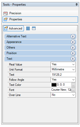
5. In Text, define:
- Real Value: define whether the real value of the dimension should be displayed or not;
- Unit Format: defines the dimension measurement format;
- Text: define the text to be displayed next to the dimension line. IMPORTANT: If this property is blank, the displayed value will be the real value of the dimension. If any value is informed, it will be displayed, as long as the Real Value property is set to No.
- Follow Angle: define whether the dimension text follows the dimension line or not, after defining the angle in the Position category.
- Text Color: set the color of the dimension value text;
- Font: define the font of the dimension value text;
- Over Line: defines whether the dimension text will be displayed on or below the dimension line;
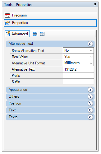
6. In Alternative Text, define:
- Show Alternative Text: define whether an alternate dimension text will be displayed or not;
- Real Value: defines whether the real value of the dimension should be displayed or not as alternative text. IMPORTANT: If this property is set to No, the text entered in the Alternative Text property is displayed.
- Alternative Unit Format: defines the dimension measurement format if the alternative text is a value;
- Alternative Text: by default, this property displays the real value of the dimension. Enter the alternative text you want to display;
- Prefix: inform the text you want to display before the alternative text;
- Suffix: inform the text you want to display after the alternative text;
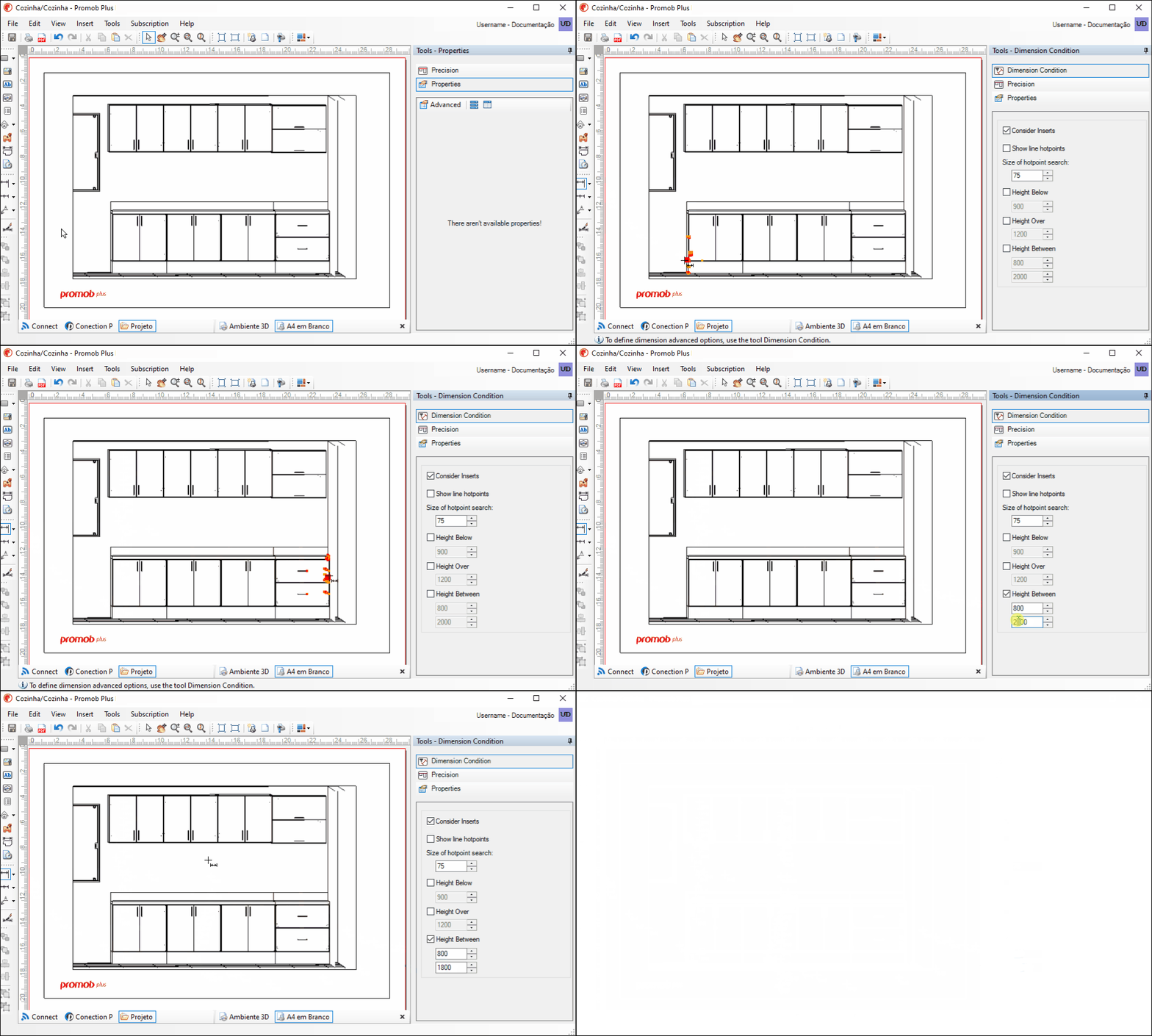
Dimension Conditions
To define the dimension conditions, perform the following procedures:
1. Insert the viewport and select one of the dimensioning options, except Quick Dimension;
2. Access Properties - Dimension Conditions.
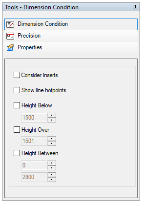
IMPORTANT: only the hotpoints of the design items that meet the dimension conditions will be displayed in the quoted viewport.
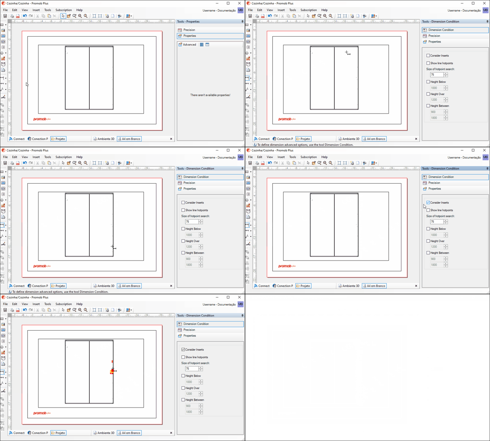
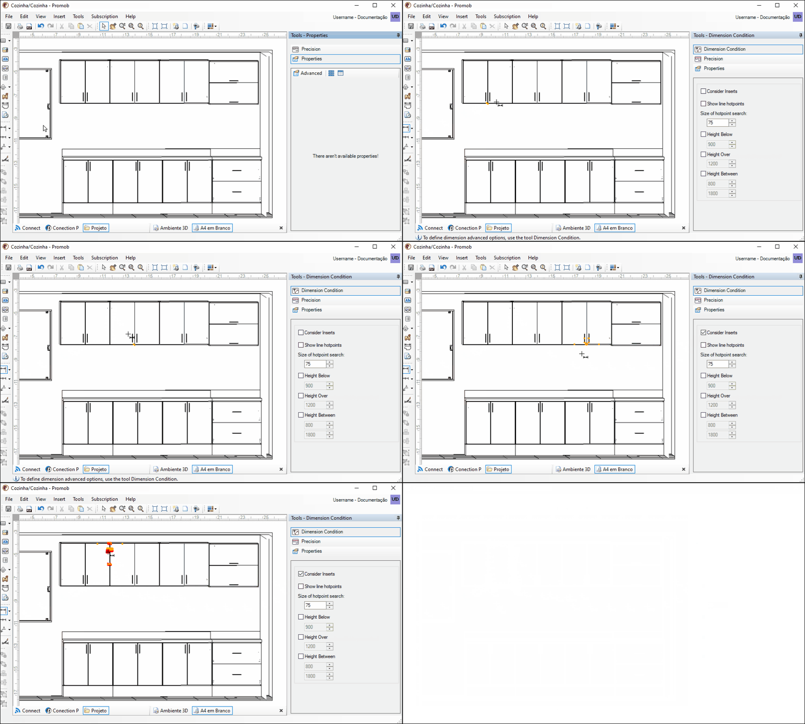
1. Consider Inserts: displays the module's insert hotpoints;
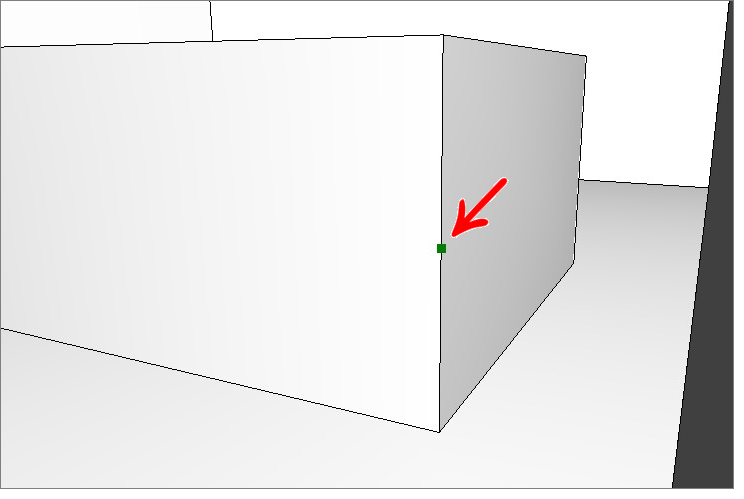
2. Show line hotpoints: allows to enable / disable line hotpoints (green hotpoints);
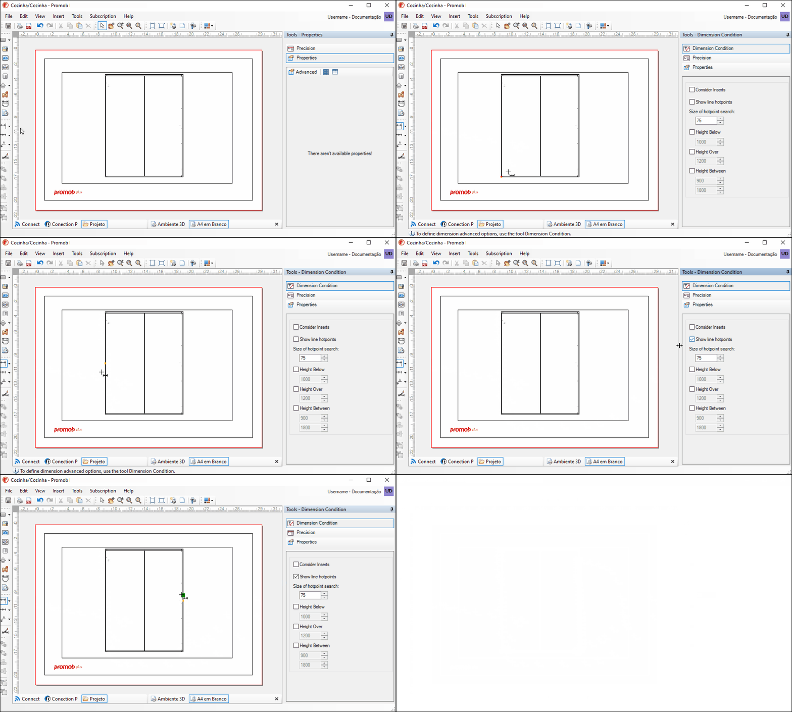
IMPORTANT: from the version Promob 5.60.15.53 it is possible to select midpoints of lines.
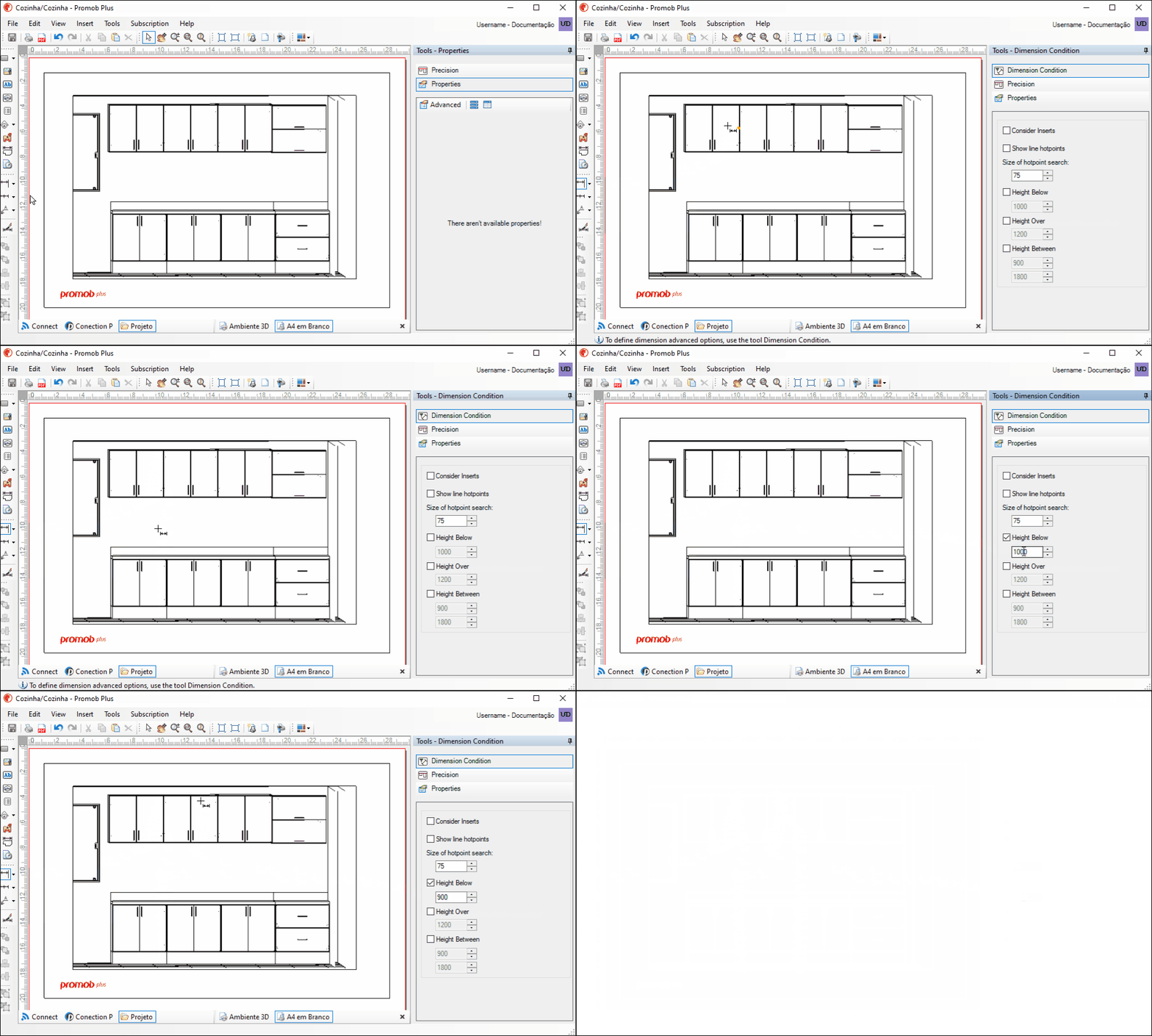
3. Height below: displays the module's hotpoints that are below the reported height;
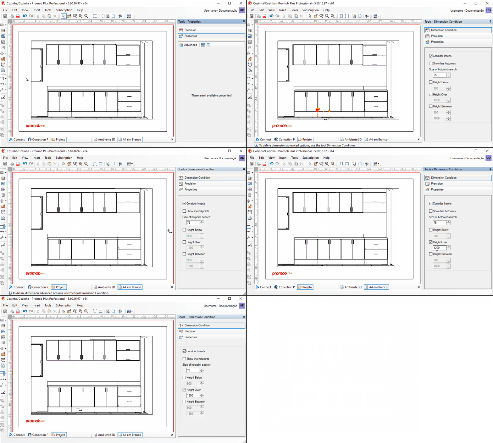
4. Height above: displays the module's hotpoints that are above the reported height;
5. Height between: displays the hotpoints of the modules that are between the informed height range.
Dimension module inserts
To dimension the inserts of the module, perform the procedures below:
1. Enable one of the dimensioning options.
2. Access Tools - Dimension Conditions and check Dimension Inserts.
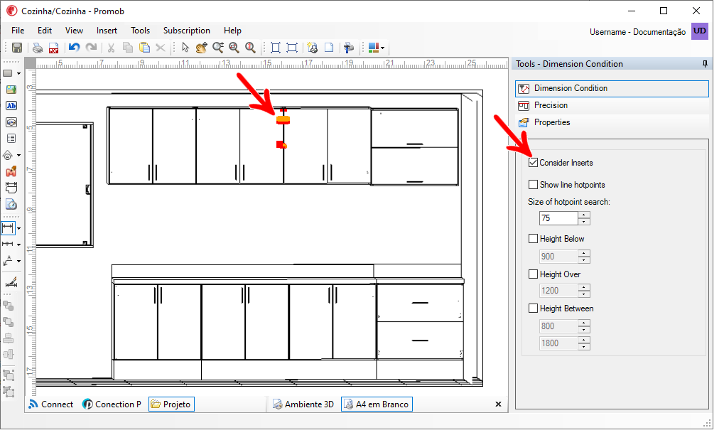
3. In the viewport, place the mouse over the insert and notice that the hotpoints are displayed. Dimension the inserts according to the type of dimension selected.
Dimension walls and openings
To size the walls and openings of a design, perform the following procedures:
1. Insert a viewport and place the design view on the floor plan:
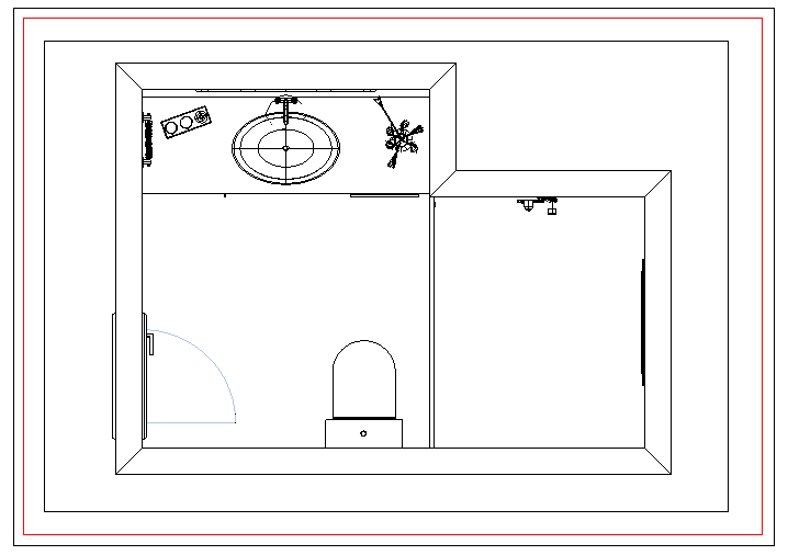
2. Enable the viewport toolbar and access the Layers window. Turn off the design layers, except Wall, Floor and Decore - Openings;
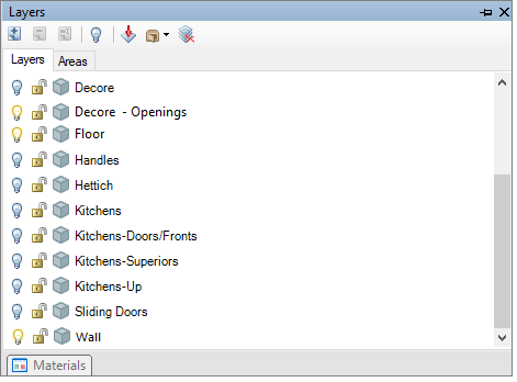
3. Dimension the walls and openings.
