Check this article for information to establish integration with machines from the manufacturer Morbidelli.
Below, select directly about one of the subjects covered in this article:
Machine programs using dimension variables
Available from version:
- Plugin Builder 1.11.27 or higher.
When making integration with Morbidelli machines, it is possible to position operations using the total dimension of the part, through the variables DX and DY in the positions of the operations, where DX indicates part measure on the X axis and DY indicates part measure on the Y axis.
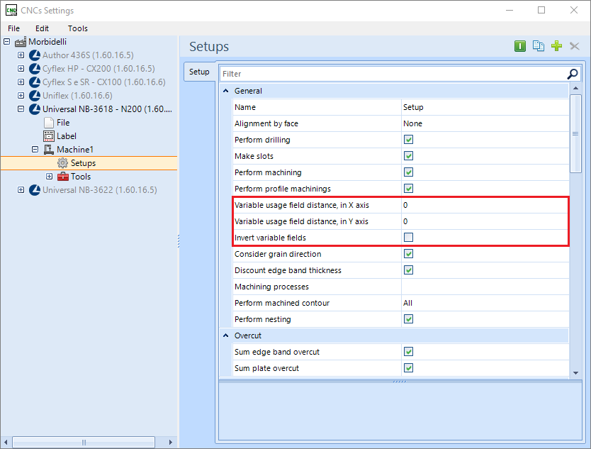
For a given operation to use the functionality, there are three fields in the machine plugin. Variable Usage Field Distance on X-axis, Variable Usage Field Distance on Y axis, and Invert variable fields.
The following topics will be covered below:
- Distance from the variable usage field on the X axis
- Distance from the field of use of variable on the Y axis
- Invert variable fields
- Field rotation
Distance from the variable usage field on the X axis
In order for the operations to consider the DX variable, they must be within an area determined by the user.
EXAMPLE:

The placed measure refers to the end of the part, so the field where the operation takes the variable, using a 1000 mm long part and the distance from the 150 mm field, as the example, should be above at least 850 mm.
Below is an illustration, where the blue area is the field where the operations must meet to take use of the variable:

Distance from the field of use of variable on the Y axis
For operations to consider the DY variable, they must be within the area determined by the user.
EXAMPLE:


Invert variable fields
The Invert variable fields option must be checked when the user wants the fields described above to invert when a part is rotated when generating the program. Below is an image of the field in the plugin and an illustration exemplifying field rotation.
EXAMPLE:

Field Rotation

EXAMPLE:
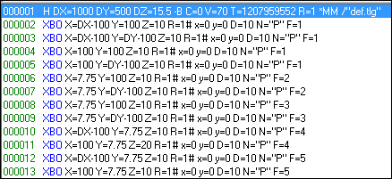
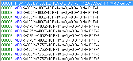
Program generated, using and not using variable functionality:
Commands using variable, machine program
Commands without using a variable, machine program
Machine program image
Promob Integration with Maestro
IMPORTANT: Maestro software and Promob must be installed on the same computer. The machine plugin needs to identify the Maestro installation on the computer for file conversion. And Maestro's hardware key needs to be connected to the computer (USB port), for Maestro's file converter to work.
For Maestro's integration with Promob:
1. Access the Options tab:
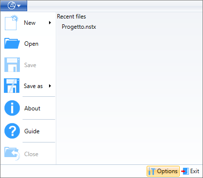
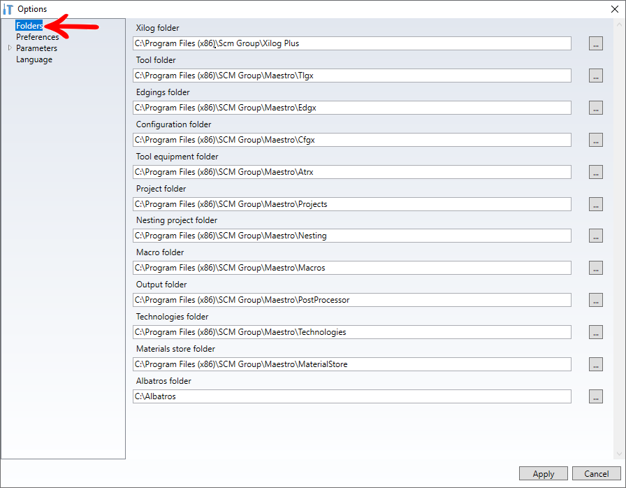
2. Configure the Folders, Preferences, and Parameters fields:
Folders:
Preferences:
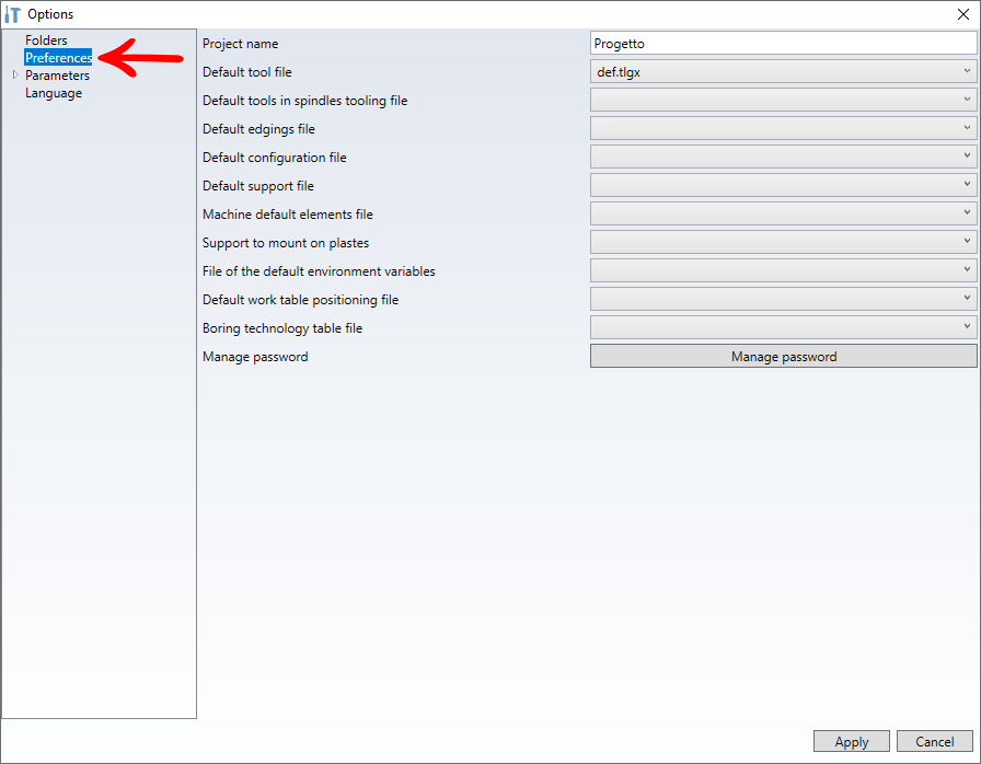
IMPORTANT: If any more options from this Preference screen are filled in, Maestro cannot import the pgmx files generated by Promob.
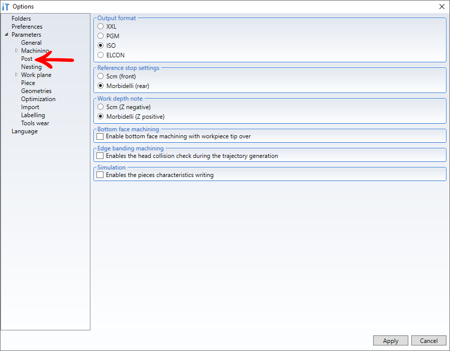
Parameters - Post
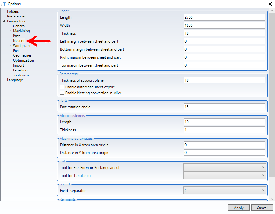
Parameters - Nesting
Promob Machine Plugins Configuration
To configure the plugin:
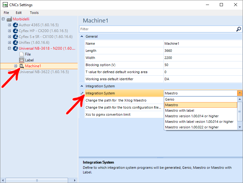
1. Go to CNC Configuration;
- In the example below, the Maestro system was selected.
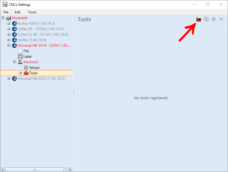
- By default, standard tools are loaded, but it is possible to import more tools;
- When doing this process, all the tools that are registered with Maestro are loaded into Promob, but when loading the tools, some of them may be loaded with an invalid parameter, so it is important to review all the tools, checking if they are correct.
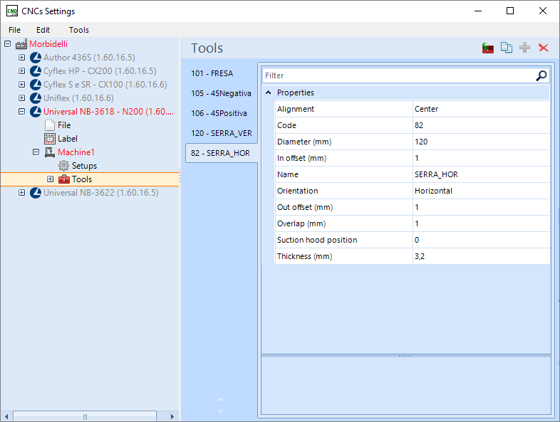
5. Within Setup, enable the usability options used, for testing purposes;
- Use as an example the configuration as shown in the image below:
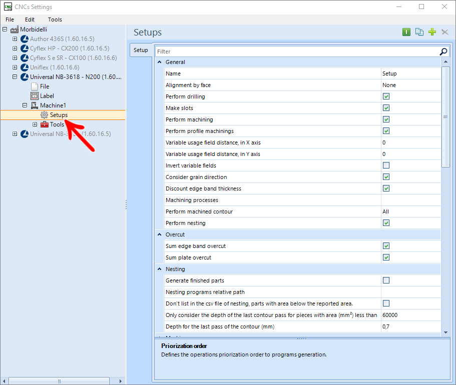
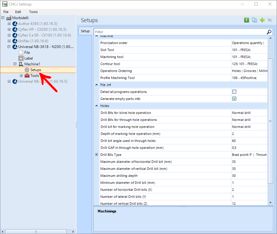
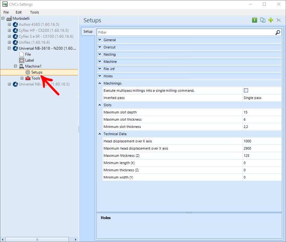
6. On machines with nesting, it is important to always work with cutters.
- For situations where there are no Spear Drills for nesting, set the Marking Drill Bit to Normal Drill
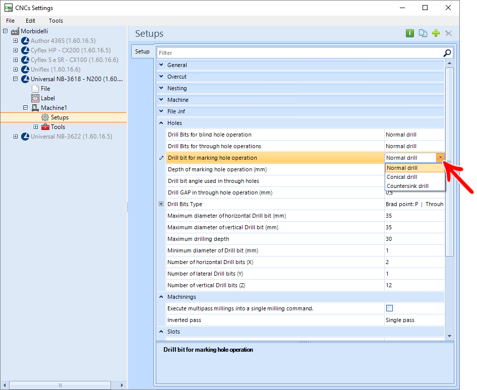
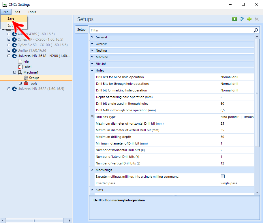
7. Once that's done, save the changes made through the File - Save menu;
Generate machine files in Promob
After a design is completed, follow the procedure below to generate the integration with the Machine:
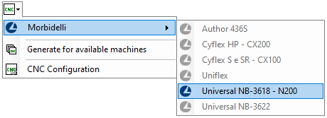
1. Generate the files for the desired machine through the CNC option - Machine Plugin;
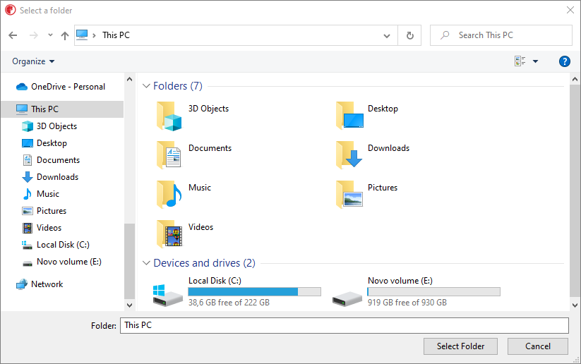
2. Select the directory where the machine files will be saved;
3. Generate Builder View technical documentation for design verification.
Import designs into Maestro
With the Maestro open, follow the procedure below:
Step 1 - Parameters
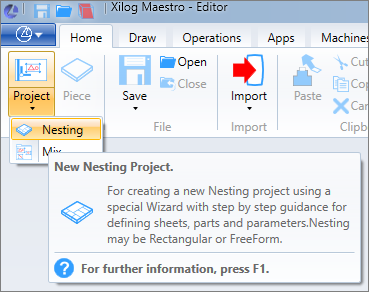
1. Click on Project and select the Nesting option.
2. In the opened window, perform the following configuration:
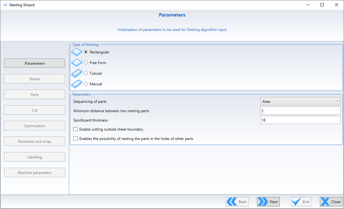
Nesting Type
- Select the Rectangular option
Parameters
- Sequence of parts select value: Select Area;
- Minimum distance between the two parts nested: Place 5 mm between the parts to have a greater security in the milling;
- Espessor do painel mártir (Thickness of the Sacrifice Plate): Select the thickness used, or keep the value of 18 mm;
- Enable cuts on the outside of the sheet: Keep Disabled;
- Abilita/disabilita la possibilità di Nestare le parte nei fori di altre parti (Enables or disables the possibility of nesting the part on the side): Keep Disabled;
Taglio
There are two ways to make this option:
1ª Option (Option Used in Test)
- Disable the field Abilita/disabilita il taglio automático delle parti (Enables/disables the automatic cut), and in the field, Larghezza massima del taglio (Maximum width of the cut) enter the diameter of the milling used in the machine.
2ª Option
- Enable the field Abilita/disabilita il taglio automático delle parti (Enables/disables the automatic cut). In the Cutting tool field, enable the used cutting tool.
Step 2 – Sheets
In this step, it is necessary to register the sheets that will be used for production.
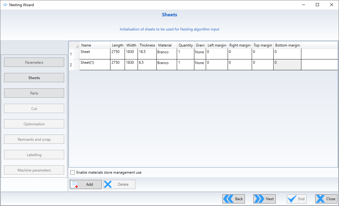
Information to be Filled in:
- Name: (Name of Plate Used Ex. Tobacco 18mm)
- Length: Total length of the plate
- Width: Plate Width
- Thickness: Sheet Thickness
- Material: Material name used exactly as it is in Promob (It can be checked in the directory where the files were generated, in the nesting folder, check the description of the .csv files)
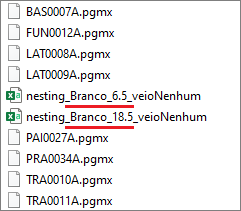
- Quantity: Quantity of available plates (Ideal always put a value of 100 so as not to block the project)
- Vertex: Bottom Left
- Direction: X
- Grain: Direction of the grain (It can be checked in the directory where the files were generated, in the nesting folder, check the description of the .csv files)
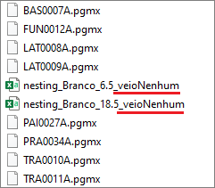
- Left Margin: Panel refill on the left margin
- Right Margin: Panel refill on the Right Margin
- Top Margin: Refining the sheet on the Top Margin
- Bottom Margin: Refining the sheet at the Bottom Margin
Step 3 – Parts
In this step, select the files generated by Promob for nesting generation.
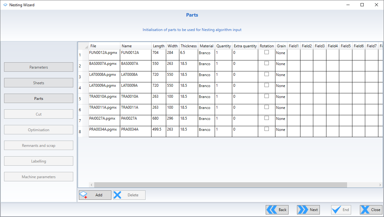
1. Click Add and select the *.csv files generated in the Nesting folder, from the directory selected when the files were generated by Promob.
- At this point, it is important to check the Thickness, Material, and Grain information registered in step 2 above, so that the imported parts contain the same information as the registered sheets.
2. After this conference, click on the End option, where a message is displayed with the generated pieces.
- This message is informed if any part is not generated.
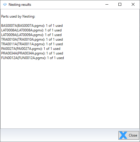
3. Click Close;
- The nesting cutting and drilling plan will be generated inside the Maestro.
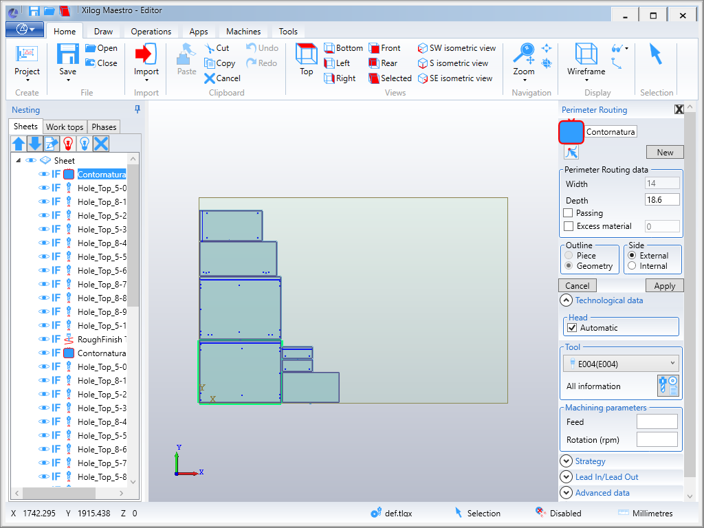
- You can see that the tree located on the left side of the screen has all the registered sheets and the operations they have on each one.
Step 4 – Optimizing operations
There are two options in this step:
1ª Option - Guided Optimization
- In this option it is possible to organize all the operations performed in the nesting, being able to organize and define which operation will be performed first;
To carry out this organization:
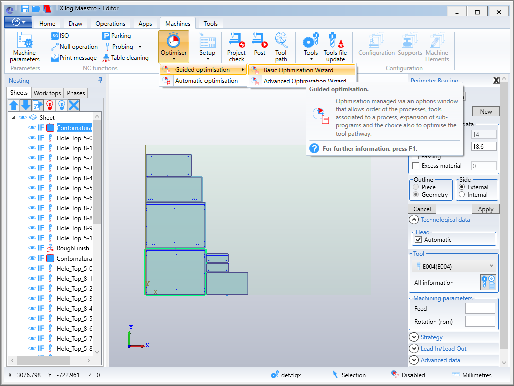
1. Access Machines- Optimiser – Guided optimisation – Basic Optimisation Wizard;
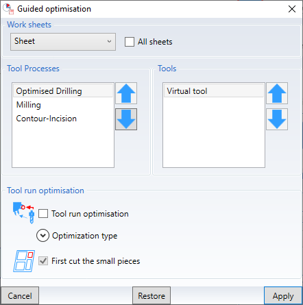
2. In the displayed window, under Worksheets, select the sheet to be used.
- It is possible to select only the sheet that you want to apply the optimization, or enable the All sheets option, thus performing the optimization for all the sheets of the nesting in question. This choice is at the discretion of the user.
2ª Option - Automatic Optimization
- In this option, Maestro himself optimizes the drilling and cutting in the best way;
For this:
1. Access the Machines- Optimizer - Automatic optimisation tab;
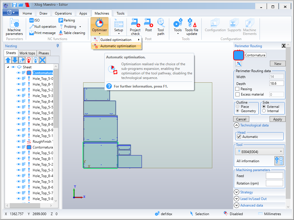
2. Select the directory where the optimization file for the machine will be generated.
Step 5 – Finish Nesting
To finish Nesting:
1. Access the Machines tab and click on Post;
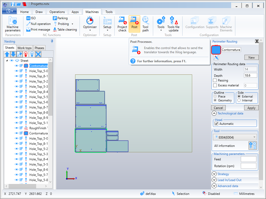
2. In the displayed window, select the plates that will be sent to the nesting machine;
3. Click Apply;
4. Select the directory where you want to save the *.mix file, to be imported by the machine into production.
5. In the displayed window, select which plates will be sent to the nesting machine;
6. Click Apply;
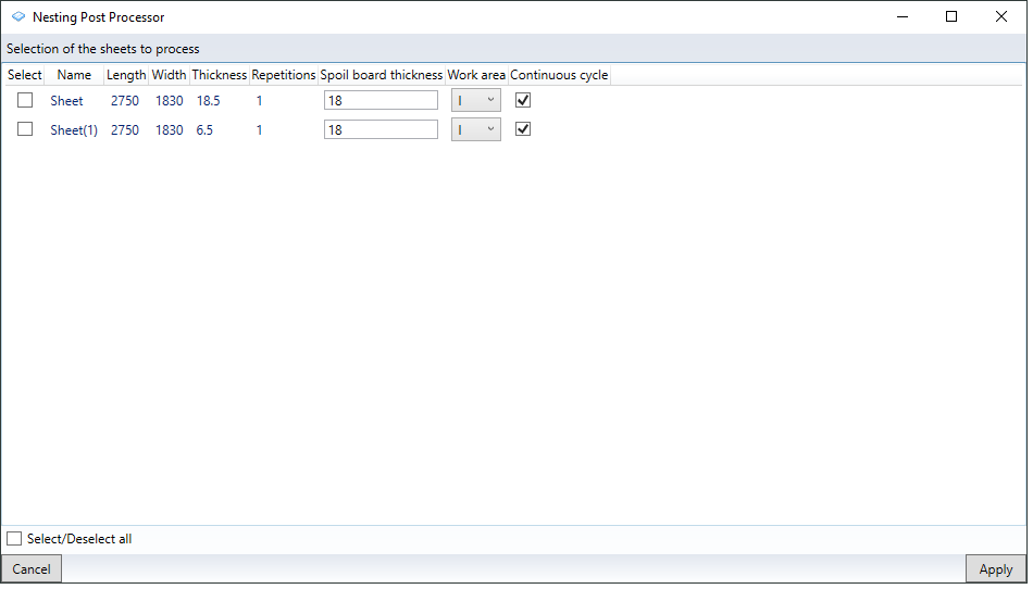
7. Select the directory where you want to save the *.mix file.
- The file is imported into production via the machine.
Integration with Genius
1. On your computer, access the Windows Settings window.
- To do this, use the Windows key on your keyboard or click on the Start menu, type Settings and click on the application.
2. In the Settings window, click on the Time and Language option;
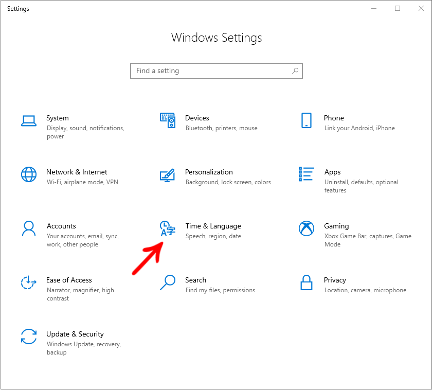
3. Click on the Region menu and select the Additional Date, Time, and Region Settings option;
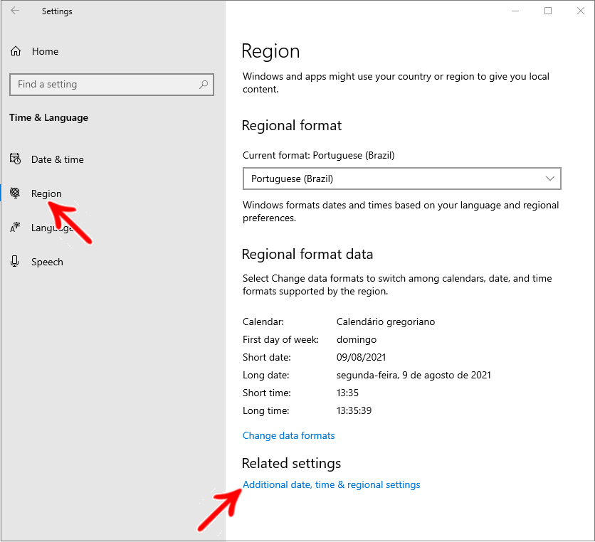
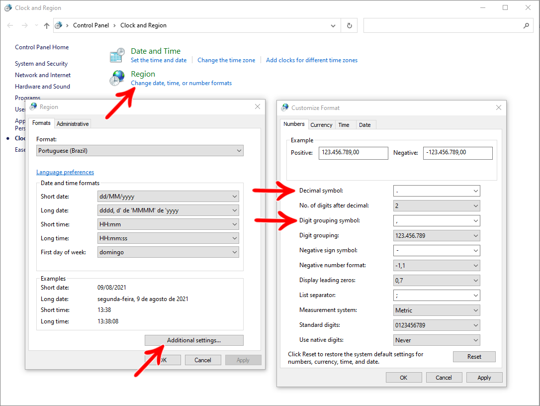
4. Click Change date, time, or number formats;
5. In the Formats tab, click Additional settings and configure:
Decimal symbol = dot ( . )
Digit grouping = comma ( , )
Import the machine's Xilog tools
1. Inside Xilog, access Tools:

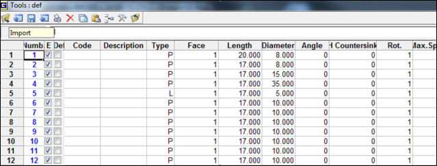
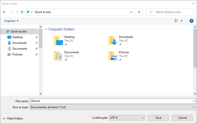
2. Select the folder where the tools file was generated.
NOTES: We have a file generated for use in the UD folder:
“S:\Builder\Builder_Novas_Definicoes\5-Maquinas_fabricantes\2-Tecmatic\Genio\Instalação Genio”
Use (Import files generated in Promob):
1. Inside Xilog, access Tools - Nesting;

2. In the Tool tool select option E1 and deselect the rectangular cut;

3. Import the nesting list generated by Promob into the directory where the *.txt was generated.


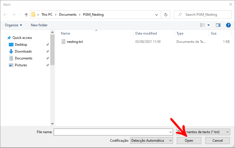
4. Check if all plates are registered in Genio, if not, register them manually.

IMPORTANT: The type must have the same name as the material used in the parts listed in the parts list exported by Promob.

5. Generate Nesting

Correction of tool "C" when integration with Genius
When the “C” tool is integrated with Genius, it is correct, regardless of the visualization in Xilog (displayed in reverse because we used C=2).
PratixS and Pratika320 viewed on Xilog:

Exporting files to Maestro
Available from version:
- Plugin Builder 1.12.12.6 or superior.
As of Maestro version 1.00.014, the files generated in Promob for Maestro are XCS or PGMX extensions. Where the PGMX is generated through the XCS file and not the XXL.
1. Select one of the Integration System options:
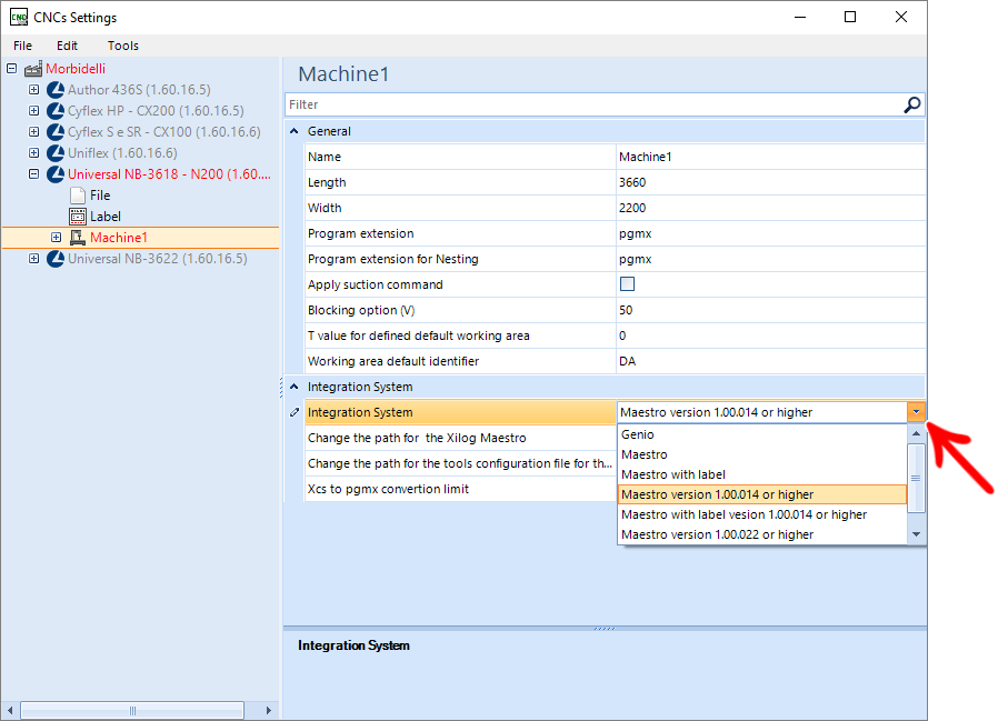
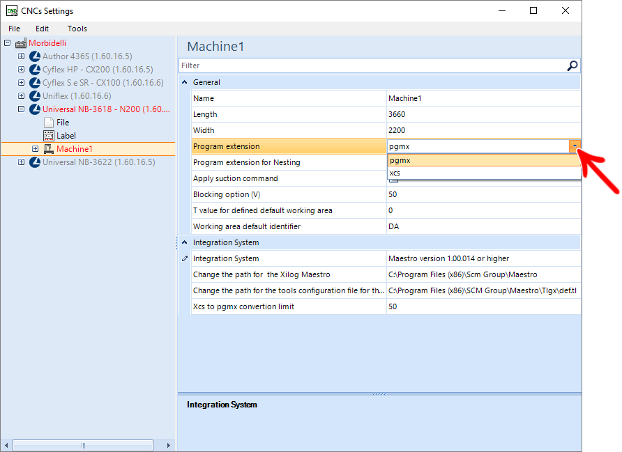
2. When selecting Maestro 1.00.014 options, define the program extension for the nesting and other folders (profile and part).
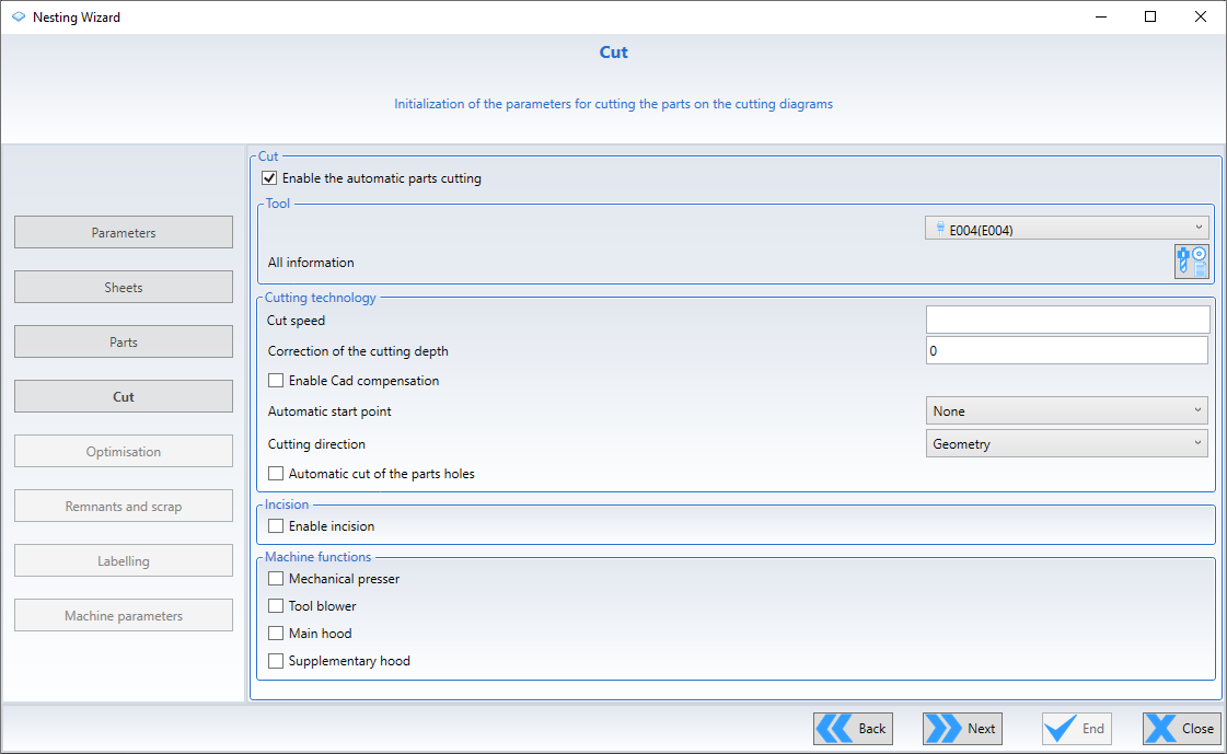
NOTES: When configured in Promob to generate files in Maestro 1.00.014 version, it is necessary to enable the Automatic parts cutting option within Maestro. With this, the outline will no longer be sent by Promob but managed by Maestro.
Head and operations prioritization
Available from versions:
- Plugin Builder 1.11.27 or superior.
- Plugin Uniflex 1.11.5 or superior.
In Setup settings, it is possible to prioritize operations so that the program selects the most “valuable” face of the part.
In addition, when enabled for both heads to perform operations, it is possible to prioritize the head, so that the program determines which head the most “valuable” face should be on.
To configure:
1. Access CNC Settings;

2. Access the machine's Setup;
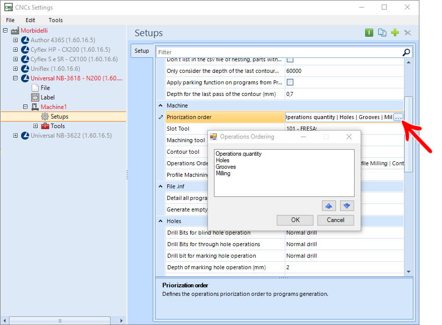
3. In the Prioritization Order field, change the order of operations using the arrows;
- The degree of importance varies from the first item on the list (most important) to the last (least important).

To prioritize the head:
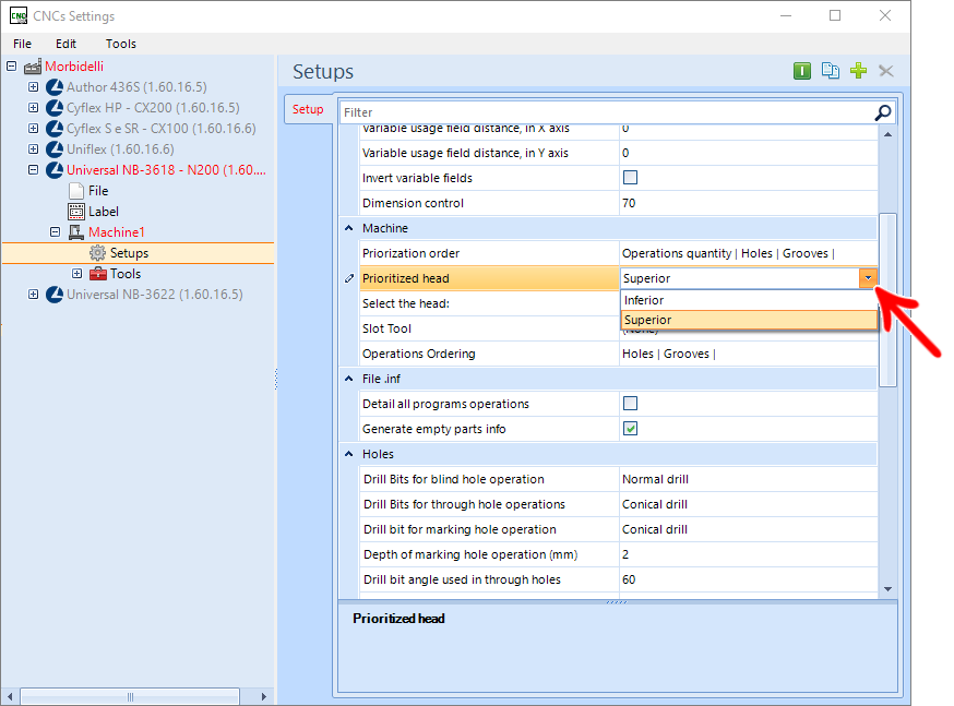
1. Access the machine's Setup;
2. In the Head to be prioritized field, select the head to be prioritized;
- This field will only be visible when the Select Head(s) field is equal to Both.
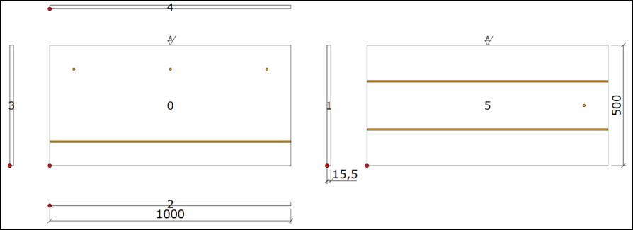
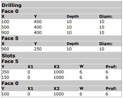
Examples using part below:
Example using only top head and prioritizing a number of operations
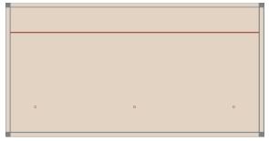
The program was generated in two parts (A and B), as only one head was selected and the part has operations on both sides. However, program A, taking into account the prioritization order, was created with the face that contains the most operations.
Plugin configuration screenshot:

Image of generated program commands:

Image of generated program A:
Example using only top head and prioritizing tears
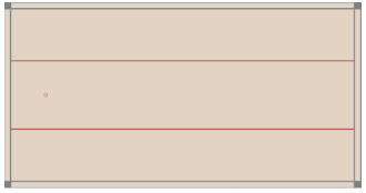
The program was generated in two parts (A and B), as only one head was selected and the part has operations on both sides. However, program A, taking into account the prioritization order, was created with the face containing the greatest number of rips.
Plugin configuration screenshot:

Image of generated program commands:

Image of generated program A:
Example using two heads, prioritizing inferior head and prioritizing number of operations
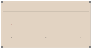
The program was generated taking into account the lower head and the number of operations, so the bottom face (F6) of the program must be the one that takes the greatest number of operations. Below are images.
Plugin configuration screenshot:

Image of generated program commands:
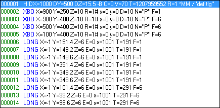
Image of the generated program:
Example using two heads, prioritizing lower head, and prioritizing tears
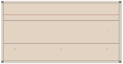
The program was generated taking into account the lower head and the number of tears, so the bottom face (F6) of the program must be the one that takes the greatest number of tears. Below are images.
Plugin configuration screenshot:

Image of generated program commands:
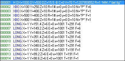
Image of the generated program:
Restriction of parts with an area smaller than the value informed Universal NB3618
Available from version:
- Plugin Builder - 1.12.11.4 or higher
For the Universal NB3618 machine, it is possible to restrict the parts listing in the *.csv file with an area value smaller than the one configured in the field Only consider last contour pass depth for parts with area (mm²) less than
For this:
1. In the Machine Setup, in the Nesting settings, check the checkbox of the option Do not list in the nesting csv file, parts with an area smaller than the informed area;
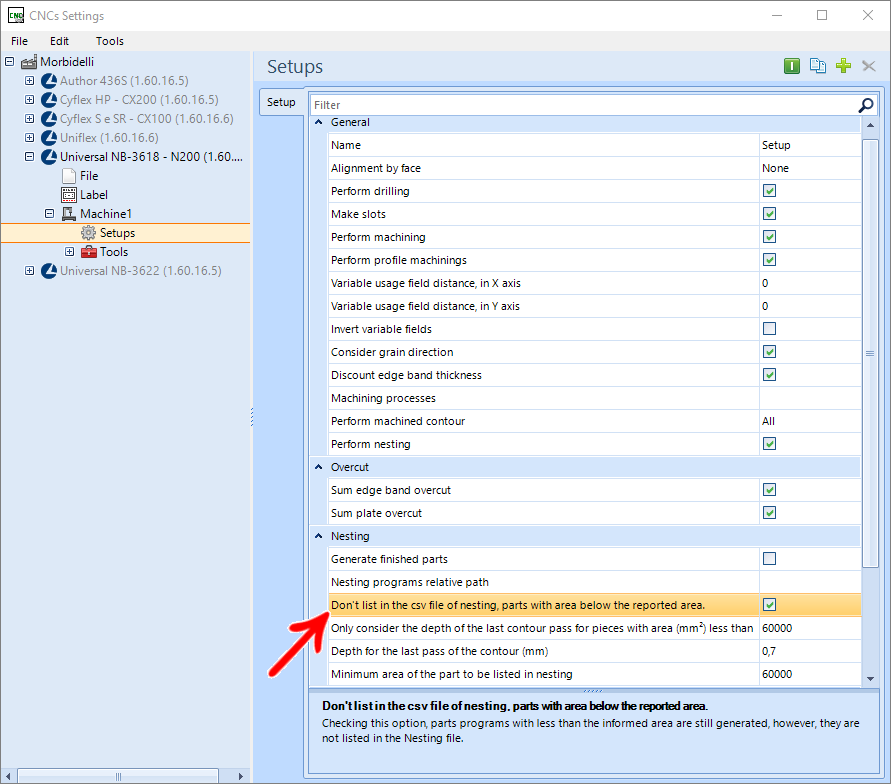
2. In the field Minimum area of the part to be listed in nesting, enter the minimum area value to be listed.
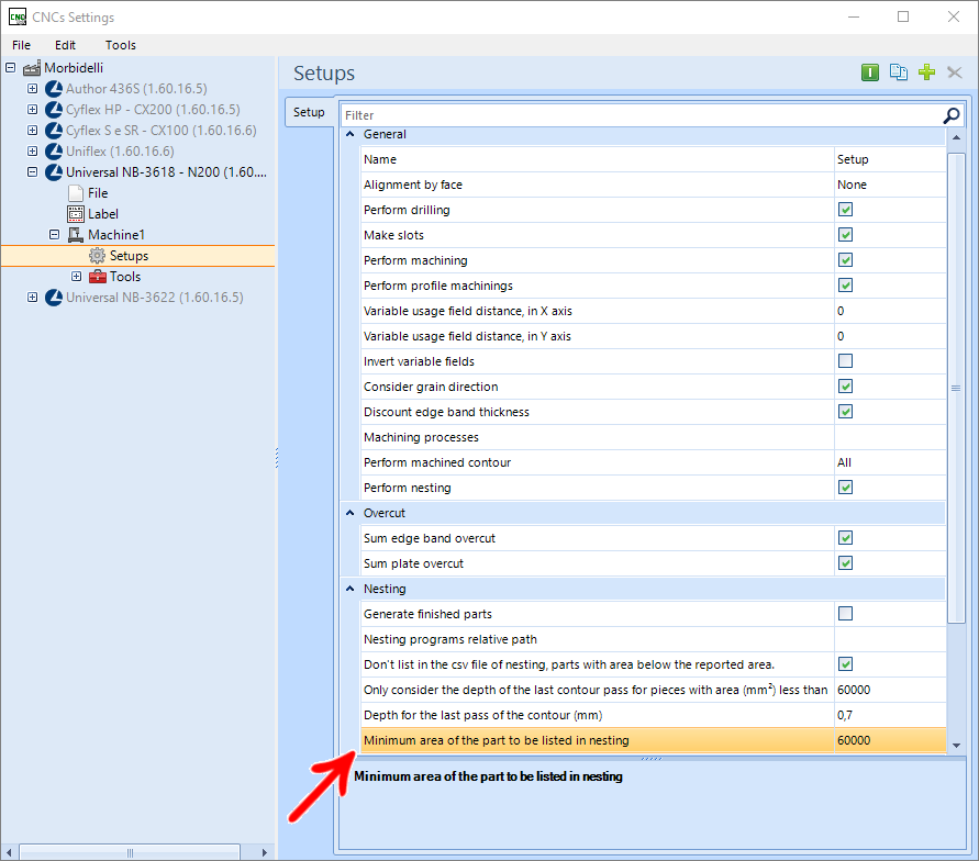

NOTES: If the field is not selected, the machine programs will always be generated in the nesting folder, including the part programs with an area smaller than the informed value. However, the programs will not be listed in the *.csv listing.
