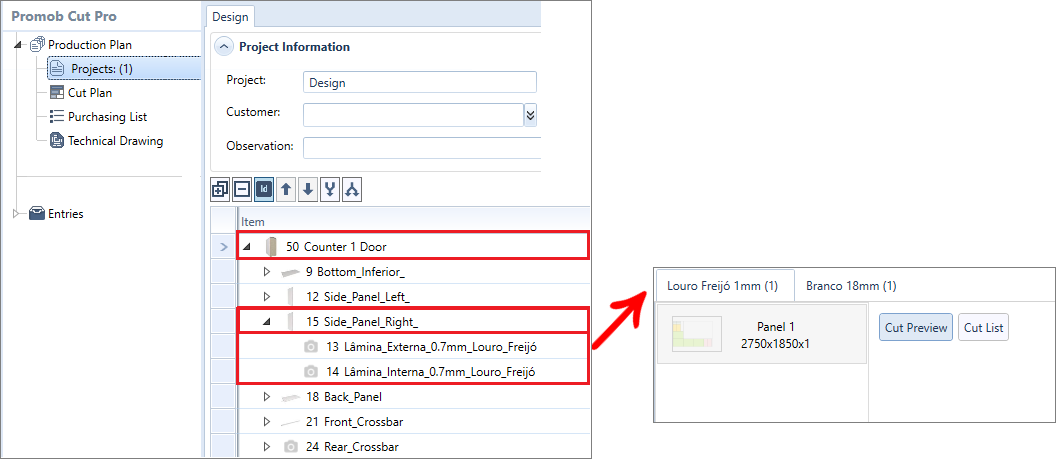
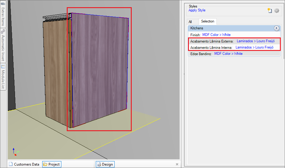
- This documentation refers to the functions performed by the Builder plugins for items that are in the 3D Environment and that have laminates or paintings applied to Models.
- As an example in this documentation, we use a Side.
Technical drawing
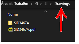
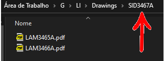
For the side, the technical drawing will be created in the following structure:
- LAT0015A.pdf: drawing of the piece on which the blade was applied;
- LAT0015A (folder): folder corresponding to the piece, in which the laminate was applied containing the drawings of the laminates;
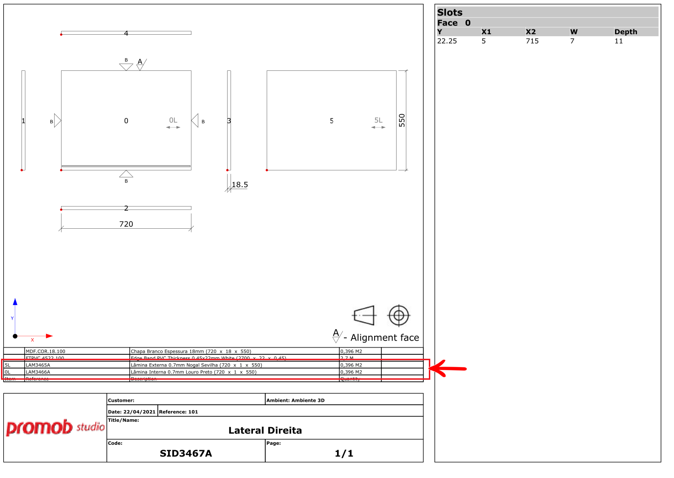
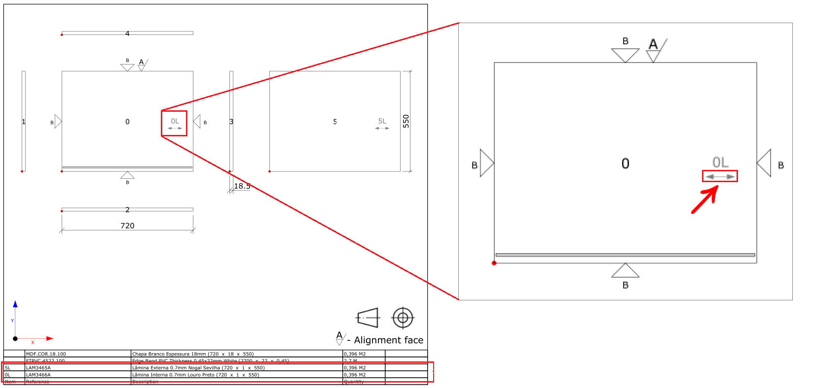
In the drawing of the piece, the applied slides will be displayed in the list of structures of the piece. The information is laminate, code, laminate description, and dimensions.
NOTES: As of Builder version 1.60.16.3, the technical drawing of the laminates represents all faces of the part, with its abbreviation and the direction of the part's vein.
The abbreviation being: face number + L

And the vein is represented by an arrow with the vein orientation on the laminate. In the example below, the laminate has a horizontal vein direction.
Inside the piece's folder, will be the drawings of the applied laminates.
Laminate application report
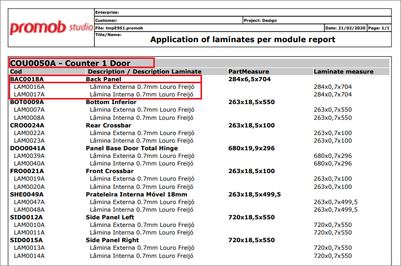
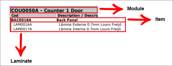
Using the Plugin Application of laminates per module report, it is possible to generate the report with the laminate information, in the following structure:
Module - Item- Laminates
For more information click here
Cutting plan
The laminates applied to an item will be sent to the cutting plane as independent pieces and will generate a cutting plane with the defined material, as follows in the Cut Pro example:
