What happens?
When assembling a module (counter, cabinet, drawer, etc.) in which there are operations generated by the Builder Plugins (holes, slots, machining, etc.), the desired fit between parts does not occur.
The situation will occur, for example, between fixing hardware holes (screws, dowel pin, minifixes, etc.) or with fitting between parts (a slot and a bottom), resulting in some misalignment between parts.
Why does it happens?
The situation can occur for different reasons, and to identify the exact cause we suggest checking the procedures described below.
What to do?
Situation 01 - Technical Drawings
The first analysis must be done with the Technical Drawings of the parts, generated through the Builder Documentation Plugins.
The Technical Drawing is a faithful representation of the item registration. Therefore, comparing the position of the operations from the Technical Drawing, it is possible to verify if it is something at the origin (library) or if it is something later.
Solution 01: If the operations are misaligned in the Technical Drawing, you must check with the person responsible for the modulation library to adjust them.
Solution 02: If the operations are aligned in the Technical Drawing, it indicates that the registration is correct. Therefore, you must proceed with the analysis of situation 02.
Situation 02 - CNC File
The second item to check is the files generated for the CNC machine where the holes were drilled.
The position of the operations in the CNC file must be identical to that represented in the Technical Drawing of the parts.
Solution 01: if the operations in the CNC file are not identical to the Technical Drawing, there may have been some inconsistency in the generation of the files. In this case, you should contact Promob's technical support.
Solution 02: if the operations in the CNC file match the Technical Drawing, it indicates that the CNC file is also correct. Therefore, you must proceed with the analysis of situation 03.
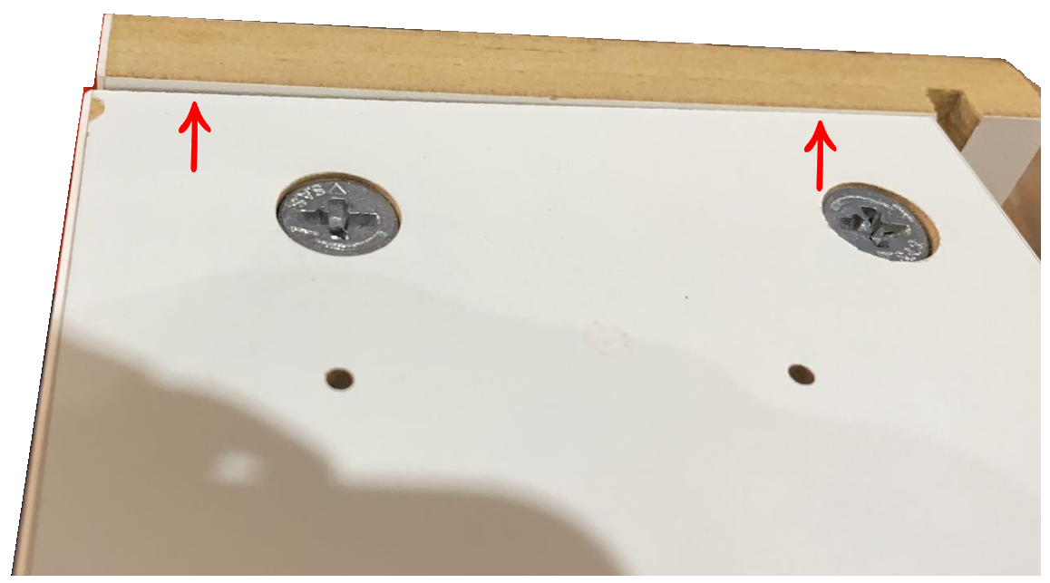
Situation 03 - Part produced
Finally, having verified that the Technical Drawing and the CNC file were generated correctly, the analysis must be performed directly on the part that was manufactured, measuring the position of the operations performed (holes, slot, etc.).
Solution 01: if the position of the operations on the part is identical to the Technical Drawing / CNC file, then theoretically they should also fit together.
Solution 02: If the position of the operations on the part is not identical to the Technical Drawing / CNC file, it is suggested that the production process be reviewed or that the technical support of the CNC machine be contacted to verify the reason for the incorrect drilling.