Some factories may have the machinery to carry out two manufacturing processes, which are generally:
Scene 1

Cut
With the design in hand, the factory must generate the integration file with the cut plan. When generating the cut plan, Promob also generates the files for the drilling centers and the images for the labels to be generated by the cut manager.
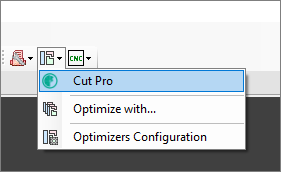
With the cut plan file in hand, the operator must import it into the cutting optimizer, perform the optimization and generate the integration for the cut manager.
IMPORTANT: Each hack optimizer plugin has its own features and functionality. Configure settings as needed for the deployment.
Edge band
The application of edge band is a non-automated process and there is no program or integration for this. Only the operator must be careful to apply the tapes according to the image present on the label that was generated by Promob.
CNC
The files for the CNC will be generated along with generating the file for the cut plane. Each part will have its CNC files, and there is the possibility that a part will have more than one program (A, B, and C). The generation of these files is based on machine restrictions and the setup performed in the plugin configuration. In each file, Promob will try to insert as many operations as possible.
It is important to note that today we cannot choose which side of the face will be side A or B, this order will always be generated automatically, depending on the number of operations on the part.
The person responsible for generating by Promob must also transfer the files to the drilling center folder, either by network or by pen drive, so that the operator can execute them.
On the machine, the operator must select the folder where the files were pasted and after that, scan the barcode of the program present on the label, which already causes the part design to be loaded into the machine software.
IMPORTANT: Each CNC plugin has its own features, tools, and setups. Configure the settings according to the parameters and needs of the deployment.
Scenery 2

Nesting (Cut)
With the design in hand, the factory must generate the integration files. Here, programs for all available machines can be generated, this way NESTING files and CNC files for drilling will be generated.
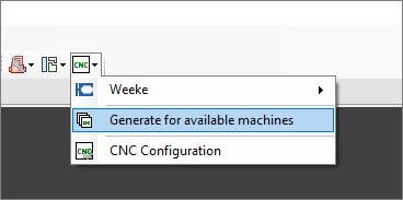
In this function, the following will be generated: the parts list for the nesting, the programs for the nesting, the secondary programs for the nesting (operations that could not be carried out in the main program), and the programs for the other drilling center.
Here, the recommended setup is that the nesting performs the drilling of finished parts only.
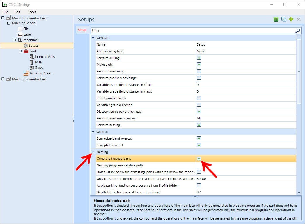
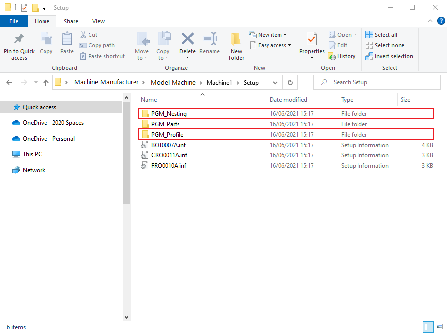
By checking this option, all parts that can be finalized in Nesting will have their operations present in the machine files in the Nesting folder, but the parts that have top and operations on the secondary face of the part will have programs created separately, in the Profile folder, generating an individual A program.
We must emphasize the importance that the holes of a part are all performed in the same machine so that, in theory, we can guarantee the alignment of the top holes with the face holes, and consequently the general alignment of the module.
Listing with the generation of Unfinished parts will generate Nesting programs, with all possible operations on the main face, generating Profile programs only for top holes or holes on the reverse face.
In both cases, the Parts folder will have all the separate features for each part of the modules, containing top holes + priority face (Drawing A) and secondary face (Drawing B).
After Promob generates the machine files, the file with the parts listing must be loaded into the machine's specific software (Maestro, BSuite3 etc.), for reading and organizing the parts for Nesting.
The software will take care of organizing the parts on the plate, generating the final file for cutting, as well as the labels.
The Nesting file will have all the information as generated in the setup configured in Promob, with contour machining, holes (if configured), always respecting the option of the finished parts. And the label generated by the machine software must contain the other production information: image for applying edge band and codes for programs A and B (when applicable).
Edge Band
The application of edge band is a non-automated process and there is no program or integration for this. Only the operator must be careful to apply the edge band according to the image present on the label that was generated by the machine software.
CNC
In the scenery where the Nesting parts will be generated FINISHED, only parts with top drilling (bases, crossbars) or with drilling on both sides (dividers, drawer sides) must pass through the CNC.
On the machine, the operator must select the folder where the files were pasted and after that, scan the barcode of the program present on the label, which already causes the part design to be loaded into the machine software.
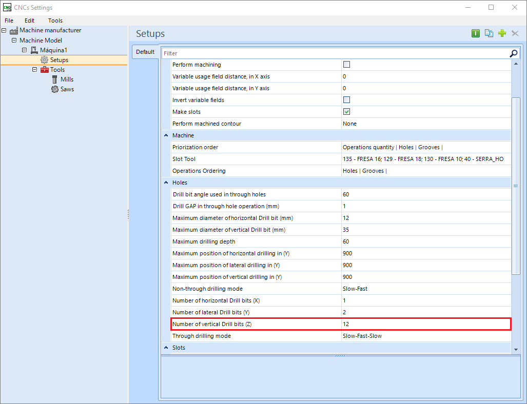
In the scenario where the parts WERE NOT FINISHED by Nesting, the CNC must have a different setup so that only the top and secondary face holes are made.
Setup Standart
Setup Tops
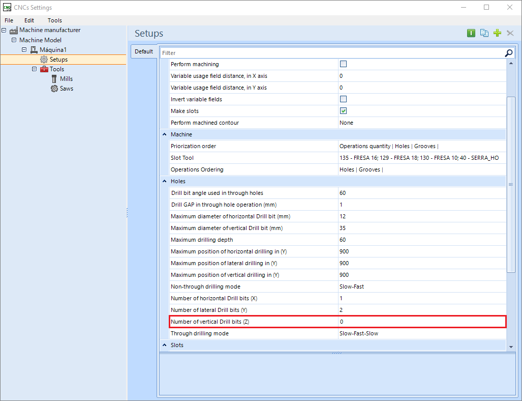
As the parts already come with the priority face with the operations performed, we have to load program A of the part that only contains the top holes, Setup Tops, and the program "B" with the operations of the secondary face, Setup Standard, where vertical drills will still be present.
In this scenery, the operator must pay much more attention, not to load the changed program and correctly place the part in the machine due to part of the holes having already been executed in the nesting.
ATTENTION: Remember that this is not a scenario we recommend, first due to the complexity of additional configuration, and then because it requires much more attention and cares with loading files and performing operations.
IMPORTANT: Each CNC plugin has its own features, tools, and setups. Configure the settings according to the parameters and needs of the deployment.