In this article, the following features of machining registration in the Plugin Builder will be addressed:
- Registration of dynamic machining
- Dynamic machining in just one module
- Application of Machining in the 3D space
- Profile machining
- Machining Use
- Machining and slot processes
- Machining Types
- Selection of parametric toolpaths
- Bridge configuration for through machining
- Machining with varying depth
- Correction in the application of dynamic contact machining
Carefully read the available material and, if you have any questions, contact Catalog Consulting.
Registration of dynamic machining
Dynamic toolpath is usually registered in items such as socket boxes, cable glands, and similar items so that, when inserted in the 3D space and positioned in a registered geometry, these accessories generate machining in the geometries to which they were added:
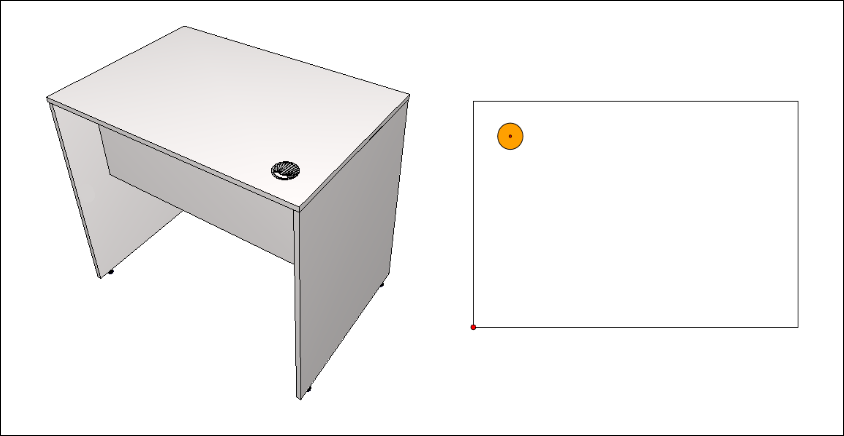
To carry out this registration it is necessary to follow the following procedures:
1. Make sure that the registered .DXF drawing has the layer registered and loaded into the drawing;
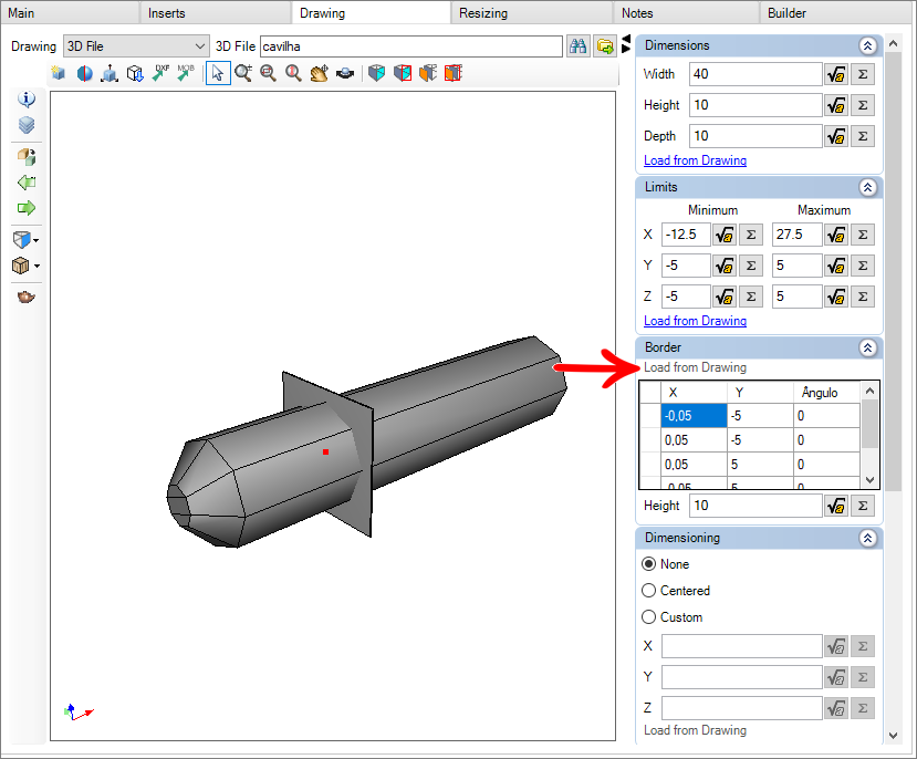
2. Within the register of the item you want to register the machining, on the Builder tab, click on the Geometries icon;
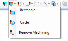
3. Select the approximate area where machining will be performed.
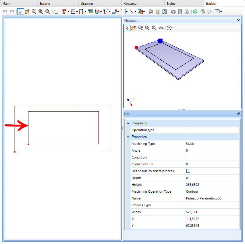

4. In the Edit window located on the right corner of the screen, it is necessary to fill in the fields to configure the toolpath;
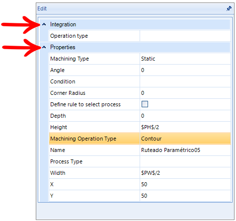
Integration
Type of operation: It will be used for budgeting and integration, this operation is registered through the Builder's operations register.
Properties
Machining Type: Defines whether the machining will be static or dynamic.
Height: Sets the height of machining.
Angle: Defines the machining angle.
Condition: In this field, rules can be determined for this toolpath to be generated or not.
Define rule for process selection: You can define a rule for process selection.
Width: Defines the machining width.
Name: Defines the name that will be given to this toolpath.
Depth: It defines the machining depth.
Radius: Defines the radius of the Machining ends.
Machining Operation Type: Defines whether the machining will be internal or contoured:
- Internal Machining: Causes all the material to be removed from the part.
- Contour Machining: Makes the milling cutter in just one pass on the part, causing part of the material to flow into the machine.
Process Type: It is possible to create and define the type of processes for specific machining registered in the Builder menu. Enabling the use of a certain tool for certain machining and not in general use for all machining.
X: Determines the X position of the hole in relation to the zero point of the part.
Y: Determines the Y position of the hole in relation to the zero point of the part.
Application of Machining in the 3D space
When inserting a dynamic toolpath in the 3D space, it will have the following functionality:
Items where machining is registered:
In these items, dynamic machining does not generate any information for production, this item serves in this case only to guide where the machining operation should be generated.
Dynamic machining can be registered in both DXF files and geometries.
Geometries in contact with dynamic machining:
For those geometries that come into contact with dynamic machining, they receive the machining operation regardless of the area where the machining made contact:
Example:

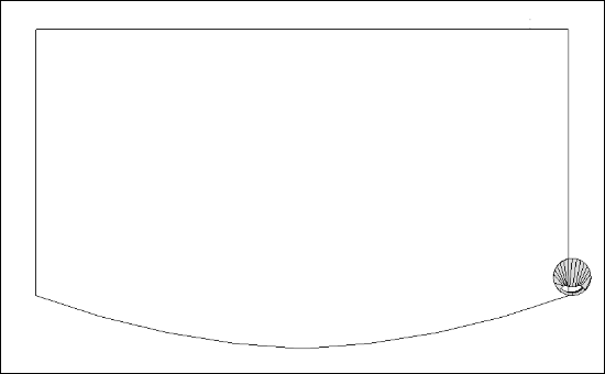
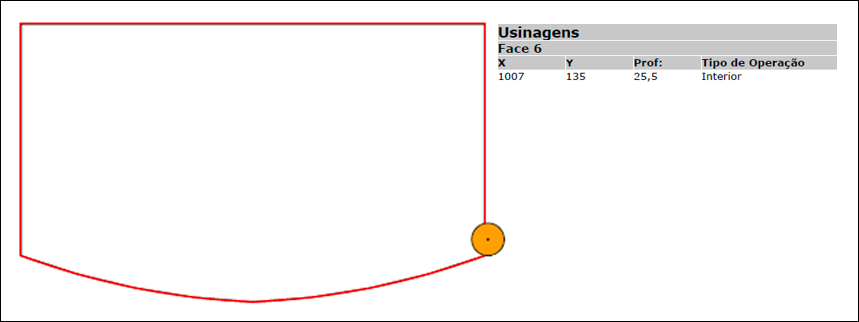
When applying rectangular dynamic machining to two parts and centering, this machining between the two parts must be 100% centered to be generated. Due to system constraints, if the machining is circular, the machining will only be generated on one part.
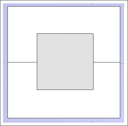
NOTE: For items registered as 3D Drawing that are inserted in the 3D space, no operations are generated at all.
Profile machining
Available from version:
- Plugin Builder 1.11.30.2
The register of profile machining can be created at an angle or not. See below how to register:
1. In the module registration, access the Builder tab and select the profile face;
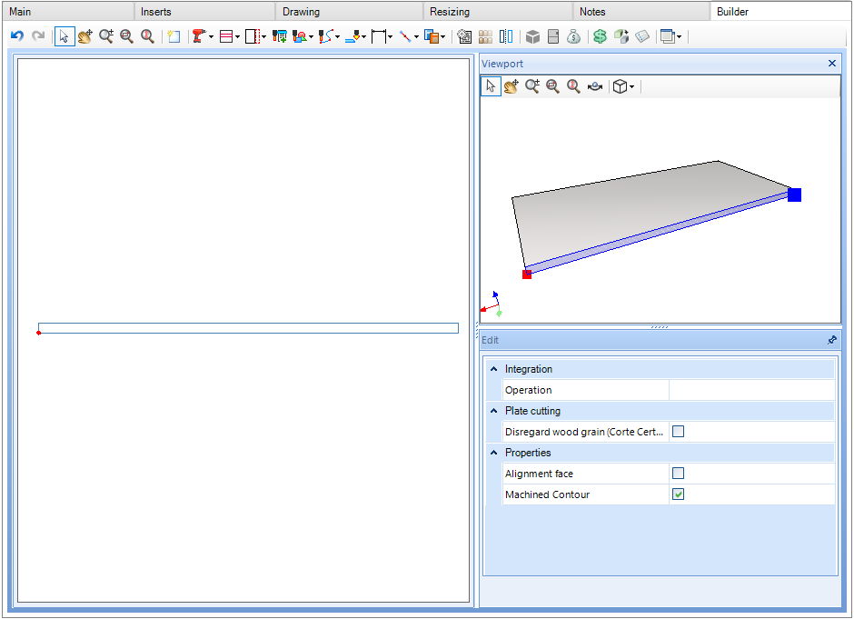
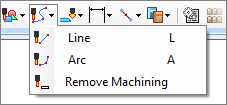
2. Select parametric machining in line and register the machining line.
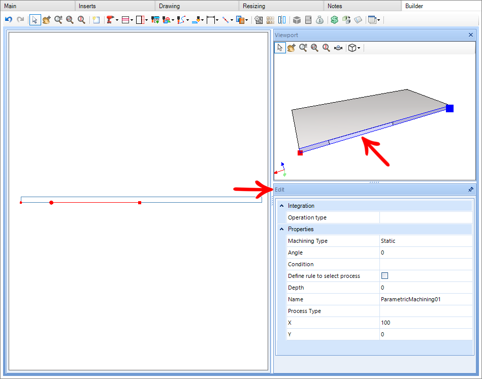

3. In the Edit field, fill in the following fields:
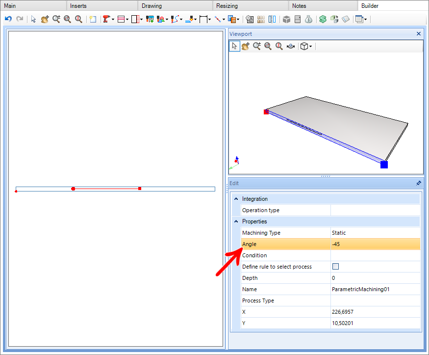
Angle: Register the machining angle referring to the tool.
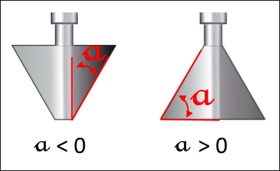
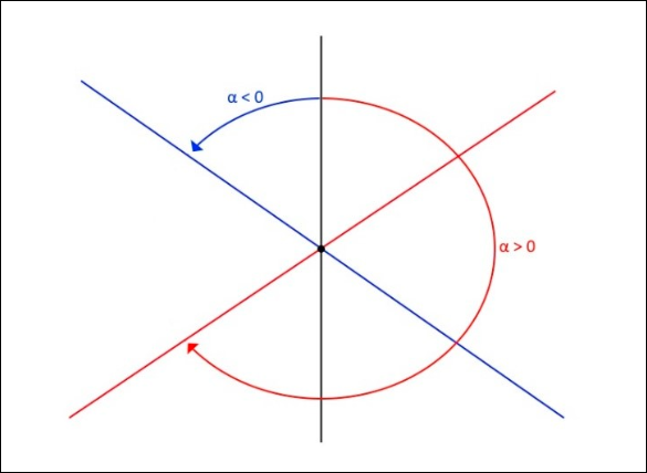
NOTE: For cases of cutters without angle, leave the value zero.
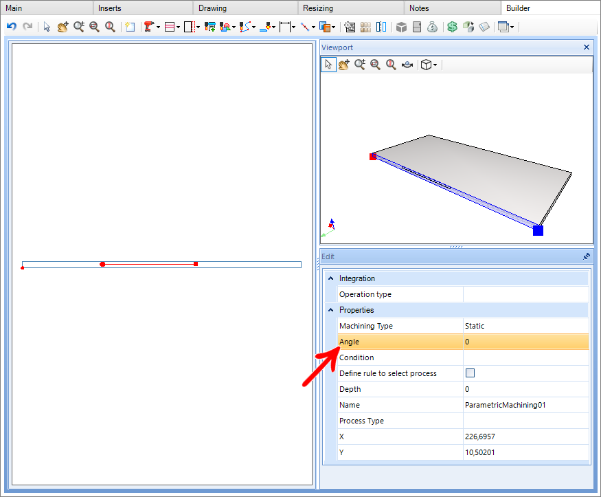
- Angle equal to zero
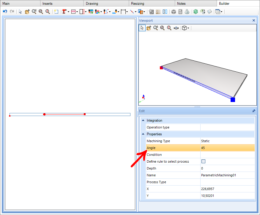
- Angle greater than zero
- Angle less than zero
1. Angle equal to zero:
2. Angle greater than zero:
3. Angle less than zero:
Setup
In CNC machine settings:
1. In the Machine Setup, check the option Perform profile machining;
2. In Tools, define compatible tools, previously registered;

1. Angle equal to zero:

2. Angle greater than zero:

3. Angle less than zero:

Tools
Currently supported tools are:
- Milling cutters: When the machining angle is equal to zero;
- Conical Mills: When the angle is different from zero;
Mill
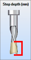
Step depth: Depth value per tool pass, depending on this value and the depth registered in the part, the number of times the tool will pass through the part is defined until reaching the desired depth.
Conical Mill
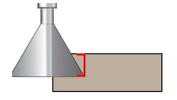
Depth of vertical pass: Value of the depth per vertical pass of the tool, depending on this value and the depth registered in the part, the number of times the tool will pass the part until reaching the desired depth vertically is defined.
IMPORTANT: As it is a new property (Builder version 1.60.16.3) and in order to maintain compatibility and standard operation, the value of the Depth of the vertical pass uses the same value as the height of the tool.
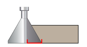
Depth of pass horizontally: Value of the depth per pass horizontally of the tool, depending on this value and the depth registered in the part, the number of times the tool will pass the part until reaching the desired depth horizontally is defined.
Diameter: Diameter of the tool.
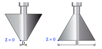
NOTE: Blue represents the zero point of the tool.
Machining compensation: Represents how far the tool goes down outside the part. This option depends on the type of angle registered:
Angle greater than zero: Only if the machining register is equal to zero on the Y axis.
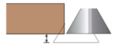
Angle less than zero:
- If the machining depth is zero regardless of the Y value;
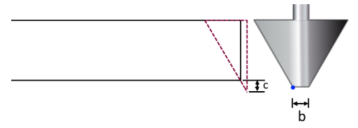
- If the depth is greater than zero and the Y value is zero.
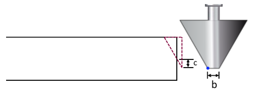
Examples:
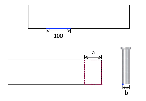
1. Machining with an angle equal to zero.
Test case 01:
| Part data | Machining angle | 0 |
| Part data | Depth | 40 mm |
| Part data | Machining starting point | X= 100, Y = 0 |
| Part data | Machining end point | X = 200, Y = 0 |
| Part data | Part size | 1000 X 500 X 15 mm |
| Part data | Diameter (b) | 10 mm |
Result:
2. Machining with an angle greater than zero.
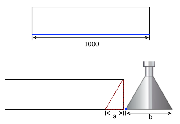
Test case 01:
| Part data | Machining angle | 45 |
| Part data | Depth (a) | 10 mm |
| Part data | Machining starting point | X= 0, Y = 0 |
| Part data | Machining end point | X = 1000, Y = 0 |
| Part data | Part size | 1000 X 500 X 15 mm |
| Tool Data | Cut angle | 45 |
| Tool Data | Diameter (b) | 60 mm |
| Tool Data | Machining compensation | 0 mm |
Result:
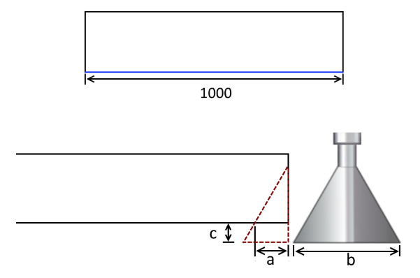
Test case 02:
| Part data | Machining angle | 45 |
| Part data | Depth (a) | 10 mm |
| Part data | Machining starting point | X= 0, Y = 0 |
| Part data | Machining end point | X = 1000, Y = 0 |
| Part data | Part size | 1000 X 500 X 15 mm |
| Tool Data | Cut angle | 45 |
| Tool Data | Diameter (b) | 60 mm |
| Tool Data | Machining compensation | 5 mm |
Result:
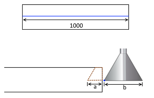
Test case 03:
| Part data | Machining angle | 45 |
| Part data | Depth (a) | 10 mm |
| Part data | Machining starting point | X= 0, Y = 7,5 |
| Part data | Machining end point | X = 1000, Y = 7,5 |
| Part data | Part size | 1000 X 500 X 15 mm |
| Tool Data | Cut angle | 45 |
| Tool Data | Diameter (b) | 60 mm |
| Tool Data | Machining compensation | 0 mm |
Result:
Test case 04:
| Part data | Machining angle | 45 |
| Part data | Depth (a) | 10 mm |
| Part data | Machining starting point | X= 0, Y = 7,5 |
| Part data | Machining end point | X = 1000, Y = 7,5 |
| Part data | Part size | 1000 X 500 X 15 mm |
| Tool Data | Cut angle | 45 |
| Tool Data | Diameter (b) | 60 mm |
| Tool Data | Machining compensation | 5 mm |
Result:
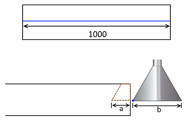
NOTE: In this case the compensation will be ignored.
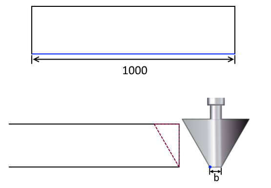
3. Machining with angle less than zero.
Test case 01:
| Part data | Machining angle | - 45 |
| Part data | Depth (a) | 0 mm |
| Part data | Machining starting point | X= 0, Y = 0 |
| Part data | Machining end point | X = 1000, Y = 0 |
| Part data | Part size | 1000 X 500 X 15 mm |
| Tool Data | Cut angle | - 45 |
| Tool Data | Diameter (b) | 20 mm |
| Tool Data | Machining compensation |
0 mm |
Result:
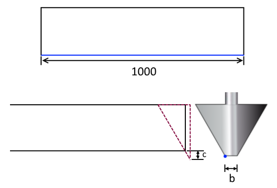
Test case 02:
| Part data | Machining angle | - 45 |
| Part data | Depth (a) | 0 mm |
| Part data | Machining starting point | X= 0, Y = 7,5 |
| Part data | Machining end point | X = 1000, Y = 7,5 |
| Part data | Part size | 1000 X 500 X 15 mm |
| Tool Data | Cut angle | - 45 |
| Tool Data | Diameter (b) | 20 mm |
| Tool Data | Machining compensation |
5 mm |
Result:
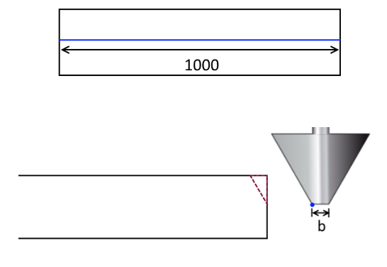
Test case 03:
| Part data | Machining angle | - 45 |
| Part data | Depth (a) | 0 mm |
| Part data | Machining starting point | X= 0, Y = 7,5 |
| Part data | Machining end point | X = 1000, Y = 7,5 |
| Part data | Part size | 1000 X 500 X 15 mm |
| Tool Data | Cut angle | - 45 |
| Tool Data | Diameter (b) | 20 mm |
| Tool Data | Machining compensation |
0 mm |
Result:
Test case 04:
| Part data | Machining angle | - 45 |
| Part data | Depth (a) | 0 mm |
| Part data | Machining starting point | X= 0, Y = 7,5 |
| Part data | Machining end point | X = 1000, Y = 7,5 |
| Part data | Part size | 1000 X 500 X 15 mm |
| Tool Data | Cut angle | - 45 |
| Tool Data | Diameter (b) | 20 mm |
| Tool Data | Machining compensation |
5 mm |
Result:
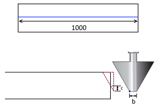
Test case 05:
| Part data | Machining angle | - 45 |
| Part data | Depth (a) | 10 mm |
| Part data | Machining starting point | X= 0, Y = 7,5 |
| Part data | Machining end point | X = 1000, Y = 7,5 |
| Part data | Part size | 1000 X 500 X 15 mm |
| Tool Data | Cut angle | - 45 |
| Tool Data | Diameter (b) | 20 mm |
| Tool Data | Machining compensation |
0 mm |
Result:
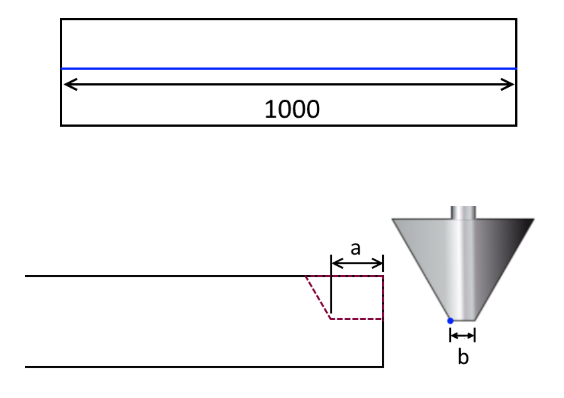
Test case 06:
| Part data | Machining angle | - 45 |
| Part data | Depth (a) | 10 mm |
| Part data | Machining starting point | X= 0, Y = 7,5 |
| Part data | Machining end point | X = 1000, Y = 7,5 |
| Part data | Part size | 1000 X 500 X 15 mm |
| Tool Data | Cut angle | - 45 |
| Tool Data | Diameter (b) | 20 mm |
| Tool Data | Machining compensation |
5 mm |
Result:
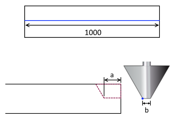
NOTE: In this case, the compensation will be ignored.
Test case 07:
|
Part data |
Machining angle |
-45 |
|
Part data |
Depth (a) |
10 mm |
|
Part data |
Machining starting point |
X = 0, Y = 2 |
|
Part data |
Machining end point |
X = 1000, Y = 2 |
|
Part data |
Part size |
1000 x 500 x 15 mm |
|
Tool Data |
Cut angle |
-45 |
|
Tool Data |
Diameter (b) |
20 mm |
|
Tool Data |
Machining compensation |
5 mm |
|
Tool Data |
Vertical stride depth (c) |
5 mm |
|
Tool Data |
Horizontal stride depth |
20 mm |
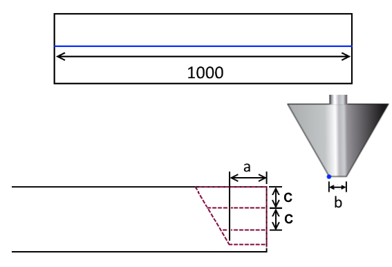
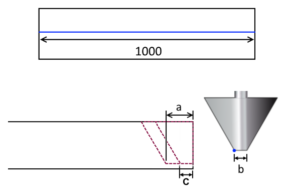
Test case 08:
|
Part data |
Machining angle |
-45 |
|
Part data |
Depth (a) |
10 mm |
|
Part data |
Machining starting point |
X = 0, Y = 2 |
|
Part data |
Machining end point |
X = 1000, Y = 2 |
|
Part data |
Part size |
1000 x 500 x 15 mm |
|
Tool Data |
Cut angle |
-45 |
|
Tool Data |
Diameter (b) |
20 mm |
|
Tool Data |
Machining compensation |
5 mm |
|
Tool Data |
Vertical stride depth |
20 mm |
|
Tool Data |
Horizontal stride depth (c) |
5 mm |
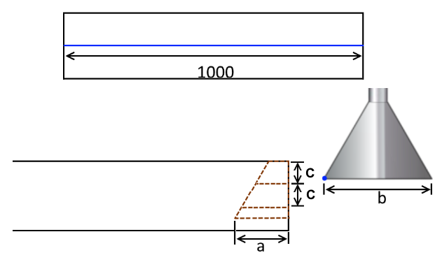
Test case 09:
|
Part data |
Machining angle |
45 |
|
Part data |
Depth (a) |
10s mm |
|
Part data |
Machining starting point |
X = 0, Y = 2 |
|
Part data |
Machining end point |
X = 1000, Y = 2 |
|
Part data |
Part size |
1000 x 500 x 15 mm |
|
Tool Data |
Cut angle |
45 |
|
Tool Data |
Diameter (b) |
20 mm |
|
Tool Data |
Machining compensation |
5 mm |
|
|
Vertical stride depth (c) |
5 mm |
|
Tool Data |
Horizontal stride depth |
20 mm |
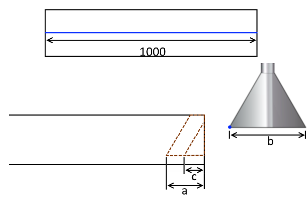
Test case 10:
|
Part data |
Machining angle |
45 |
|
Part data |
Depth (a) |
10ss mm |
|
Part data |
Machining starting point |
X = 0, Y = 2 |
|
Part data |
Machining end point |
X = 1000, Y = 2 |
|
Part data |
Part size |
1000 x 500 x 15 mm |
|
Tool Data |
Cut angle |
45 |
|
Tool Data |
Diameter (b) |
20 mm |
|
Tool Data |
Machining compensation |
5 mm |
|
Tool Data |
Vertical stride depth |
20 mm |
|
Tool Data |
Horizontal stride depth (c) |
5 mm |
Examples of generated programs
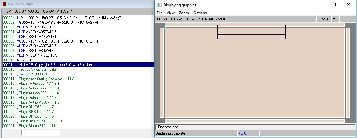
1. Profile machining within the limits of the part:
- Angle equal to zero:
| Part data | Machining angle | 0 |
| Part data | Depth | 60 mm |
| Part data | Machining starting point | X= 330, Y = 0 |
| Part data | Machining end point | X = 710, Y = 0 |
| Part data | Part size | 1000 X 500 X 18,5 mm |
| Tool Data | Diameter | 16 mm |
| Tool Data | Machining direction | Clockwise |
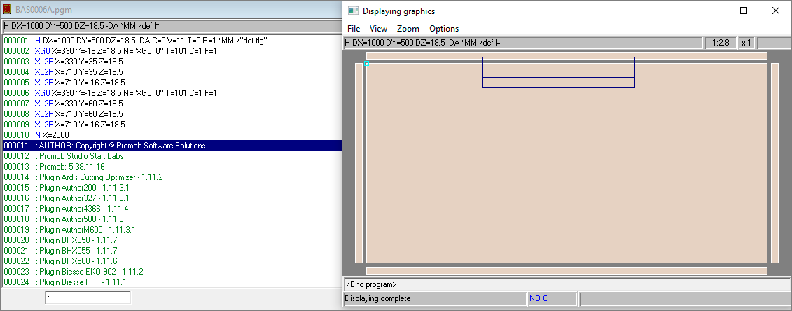
| Part data | Machining angle | 0 |
| Part data | Depth | 60 mm |
| Part data | Machining starting point | X= 330, Y = 0 |
| Part data | Machining end point | X = 710, Y = 0 |
| Part data | Part size | 1000 X 500 X 18,5 mm |
| Tool Data | Diameter | 16 mm |
| Tool Data | Machining direction | Counter-clockwise |
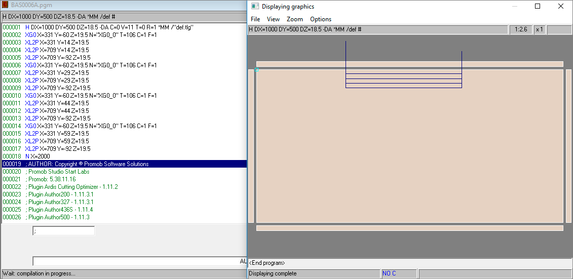
- Angle greater than zero:
| Part data | Machining angle | 45 |
| Part data | Depth | 60 mm |
| Part data | Machining starting point | X= 330, Y = 0 |
| Part data | Machining end point | X = 710, Y = 0 |
| Part data | Part size | 1000 X 500 X 18,5 mm |
| Tool Data | Cut angle | 45 |
| Tool Data | Diameter | 60 mm |
| Tool Data | Machining compensation | 1 mm |
| Tool Data | Machining direction | Clockwise |
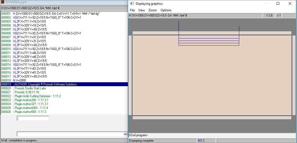
| Part data | Machining angle | 45 |
| Part data | Depth | 60 mm |
| Part data | Machining starting point | X= 330, Y = 0 |
| Part data | Machining end point | X = 710, Y = 0 |
| Part data | Part size | 1000 X 500 X 18,5 mm |
| Tool Data | Cut angle | 45 |
| Tool Data | Diameter | 60 mm |
| Tool Data | Machining compensation | 1 mm |
| Tool Data | Machining direction | Counter-clockwise |
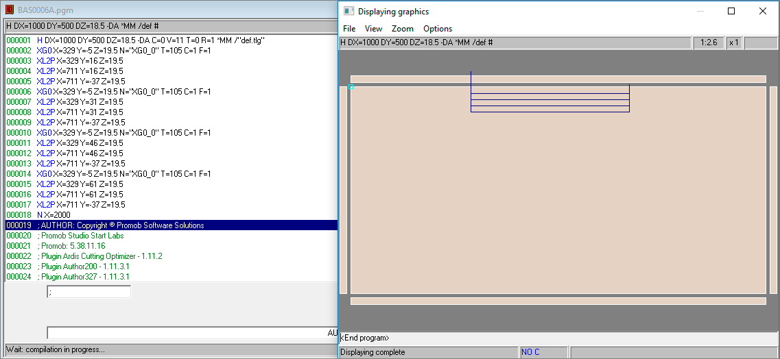
- Angle less than zero:
| Part data | Machining angle | - 45 |
| Part data | Depth | 60 mm |
| Part data | Machining starting point | X= 330, Y = 0 |
| Part data | Machining end point | X = 710, Y = 0 |
| Part data | Part size | 1000 X 500 X 18,5 mm |
| Tool Data | Cut angle | - 45 |
| Tool Data | Diameter | 5 mm |
| Tool Data | Machining compensation | 1 mm |
| Tool Data | Machining direction | Clockwise |
| Part data | Machining angle | - 45 |
| Part data | Depth | 60 mm |
| Part data | Machining starting point | X= 330, Y = 0 |
| Part data | Machining end point | X = 710, Y = 0 |
| Part data | Part size | 1000 X 500 X 18,5 mm |
| Tool Data | Cut angle | - 45 |
| Tool Data | Diameter | 5 mm |
| Tool Data | Machining compensation | 1 mm |
| Tool Data | Machining direction | Counter-clockwise |
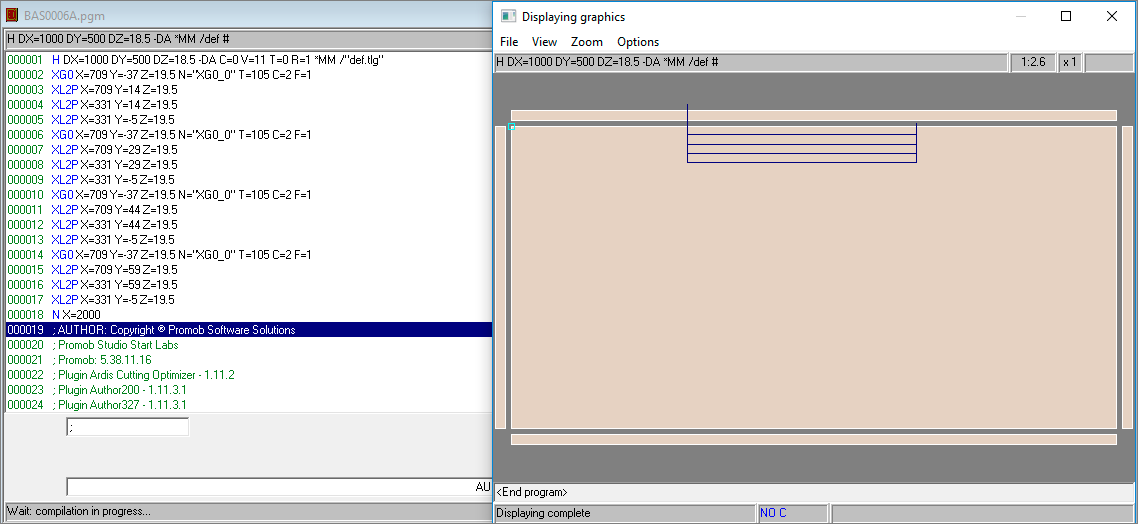
2. Machining the profile from the outside to the inside of the part:
- Angle equal to zero:
| Part data | Machining angle | 0 |
| Part data | Depth | 60 mm |
| Part data | Machining starting point | X= - 40, Y = 5 |
| Part data | Machining end point | X = 340, Y = 5 |
| Part data | Part size | 1000 X 500 X 18,5 mm |
| Tool Data | Diameter | 16 mm |
| Tool Data | Machining direction | Clockwise |
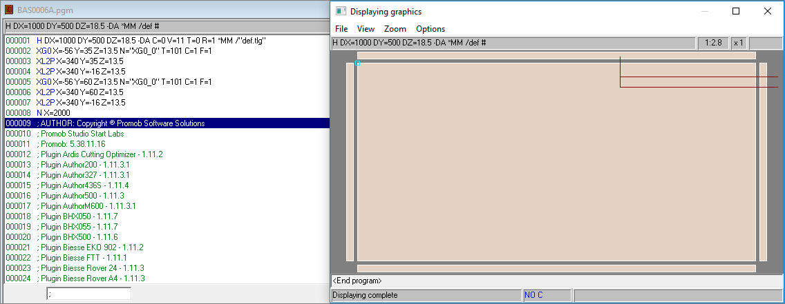
| Part data | Machining angle | 0 |
| Part data | Depth | 60 mm |
| Part data | Machining starting point | X= - 40, Y = 5 |
| Part data | Machining end point | X = 340, Y = 5 |
| Part data | Part size | 1000 X 500 X 18,5 mm |
| Tool Data | Diameter | 16 mm |
| Tool Data | Machining direction | Counter-clockwise |
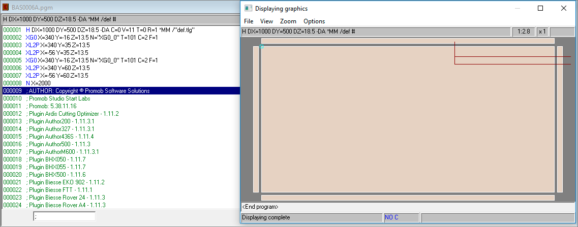
- Angle greater than zero:
| Part data | Machining angle | 45 |
| Part data | Depth | 60 mm |
| Part data | Machining starting point | X= -40, Y = 5 |
| Part data | Machining end point | X = 340, Y = 5 |
| Part data | Part size | 1000 X 500 X 18,5 mm |
| Tool Data | Cut angle | 45 |
| Tool Data | Diameter | 60 mm |
| Tool Data | Machining compensation | 1 mm |
| Tool Data | Machining direction | Clockwise |
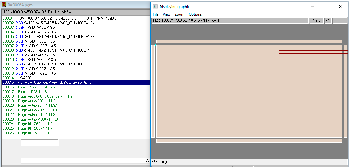
| Part data | Machining angle | 45 |
| Part data | Depth | 60 mm |
| Part data | Machining starting point | X= -40, Y = 5 |
| Part data | Machining end point | X = 340, Y = 5 |
| Part data | Part size | 1000 X 500 X 18,5 mm |
| Tool Data | Cut angle | 45 |
| Tool Data | Diameter | 60 mm |
| Tool Data | Machining compensation | 1 mm |
| Tool Data | Machining direction | Counter-clockwise |
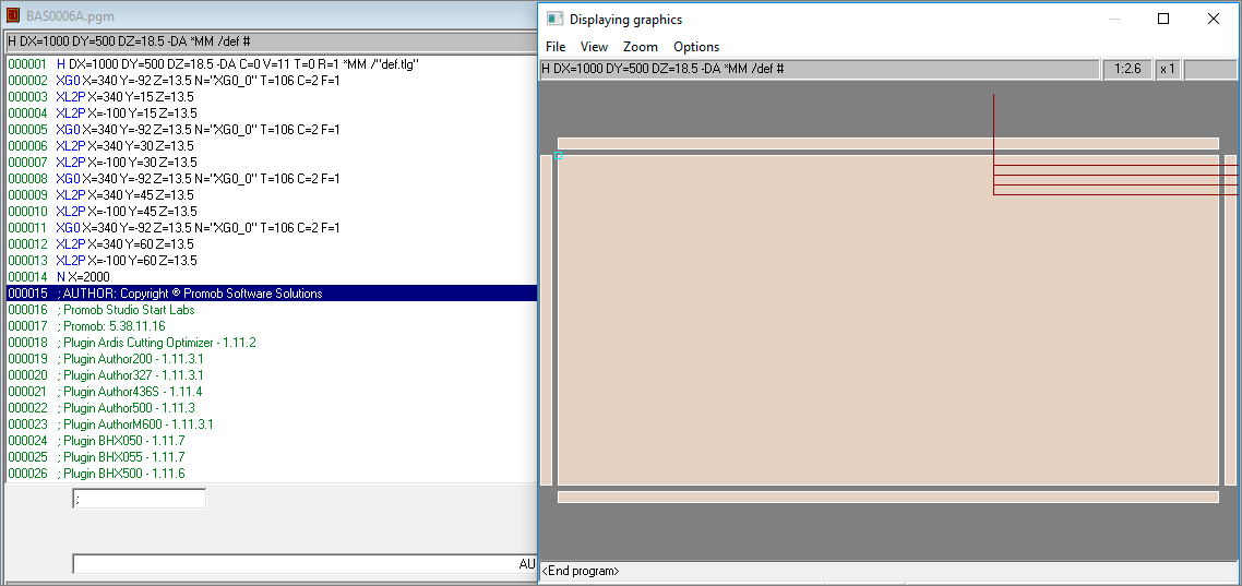
- Angle less than zero:
| Part data | Machining angle | - 45 |
| Part data | Depth | 60 mm |
| Part data | Machining starting point | X= - 40, Y = 5 |
| Part data | Machining end point | X = 340, Y = 5 |
| Part data | Part size | 1000 X 500 X 18,5 mm |
| Tool Data | Cut angle | - 45 |
| Tool Data | Diameter | 5 mm |
| Tool Data | Machining compensation | 1 mm |
| Tool Data | Machining direction | Clockwise |
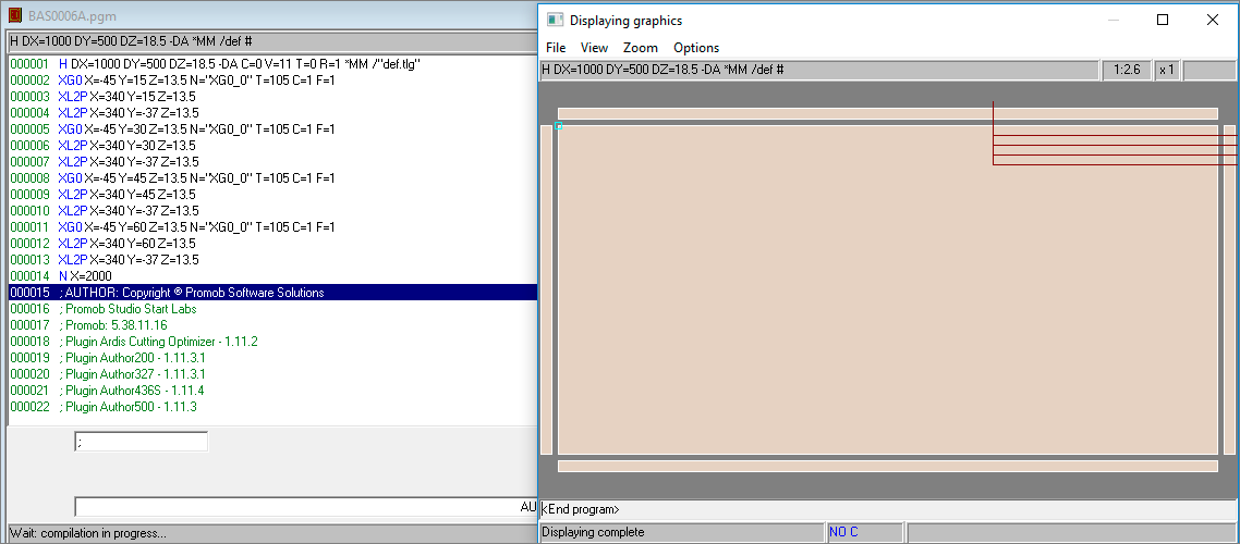
| Part data | Machining angle | - 45 |
| Part data | Depth | 60 mm |
| Part data | Machining starting point | X= - 40, Y = 5 |
| Part data | Machining end point | X = 340, Y = 5 |
| Part data | Part size | 1000 X 500 X 18,5 mm |
| Tool Data | Cut angle | - 45 |
| Tool Data | Diameter | 5 mm |
| Tool Data | Machining compensation | 1 mm |
| Tool Data | Machining direction | Counter-clockwise |
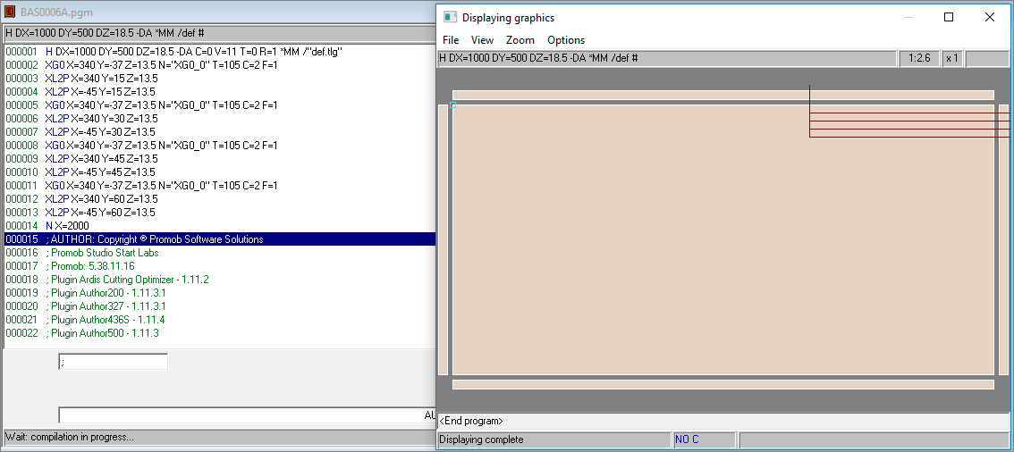
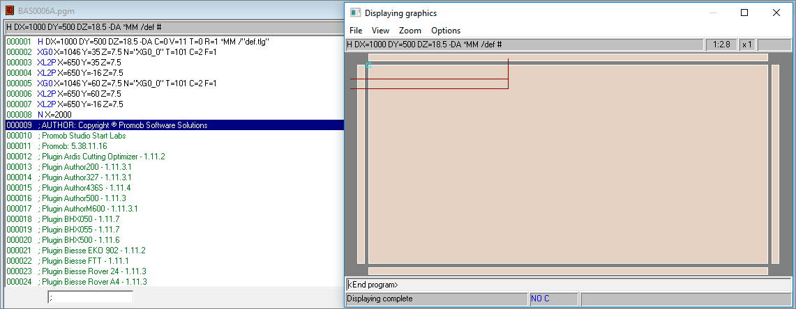
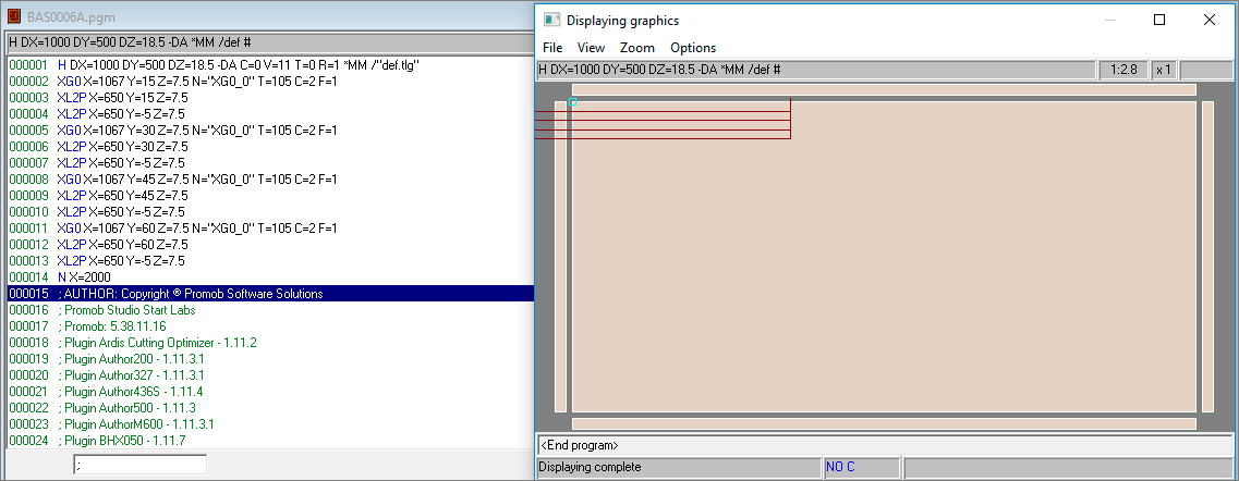
3. Profile machining from the inside to the outside of the part:
- Angle equal to zero:
| Part data | Machining angle | 0 |
| Part data | Depth | 60 mm |
| Part data | Machining starting point | X= 650, Y = 11 |
| Part data | Machining end point | X = 1030, Y = 11 |
| Part data | Part size | 1000 X 500 X 18,5 mm |
| Tool Data | Diameter | 16 mm |
| Tool Data | Machining direction | Clockwise |
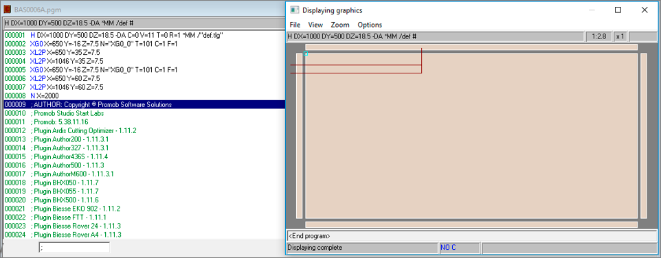
| Part data | Machining angle | 0 |
| Part data | Depth | 60 mm |
| Part data | Machining starting point | X= 650, Y = 11 |
| Part data | Machining end point | X = 1030, Y = 11 |
| Part data | Part size | 1000 X 500 X 18,5 mm |
| Tool Data | Diameter | 16 mm |
| Tool Data | Machining direction | Counter-clockwise |
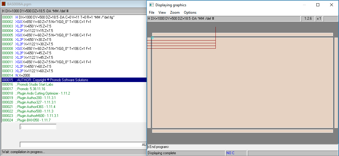
- Angle greater than zero:
| Part data | Machining angle | 45 |
| Part data | Depth | 60 mm |
| Part data | Machining starting point | X= 650, Y = 11 |
| Part data | Machining end point | X = 1030, Y = 11 |
| Part data | Part size | 1000 X 500 X 18,5 mm |
| Tool Data | Cut angle | 45 |
| Tool Data | Diameter | 60 mm |
| Tool Data | Machining compensation | 1 mm |
| Tool Data | Machining direction | Clockwise |
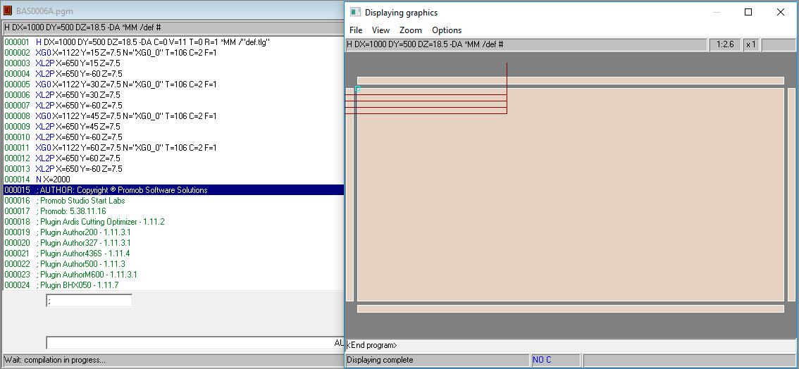
| Part data | Machining angle | 45 |
| Part data | Depth | 60 mm |
| Part data | Machining starting point | X= 650, Y = 11 |
| Part data | Machining end point | X = 1030, Y = 11 |
| Part data | Part size | 1000 X 500 X 18,5 mm |
| Tool Data | Cut angle | 45 |
| Tool Data | Diameter | 60 mm |
| Tool Data | Machining compensation | 1 mm |
| Tool Data | Machining direction | Counter-clockwise |
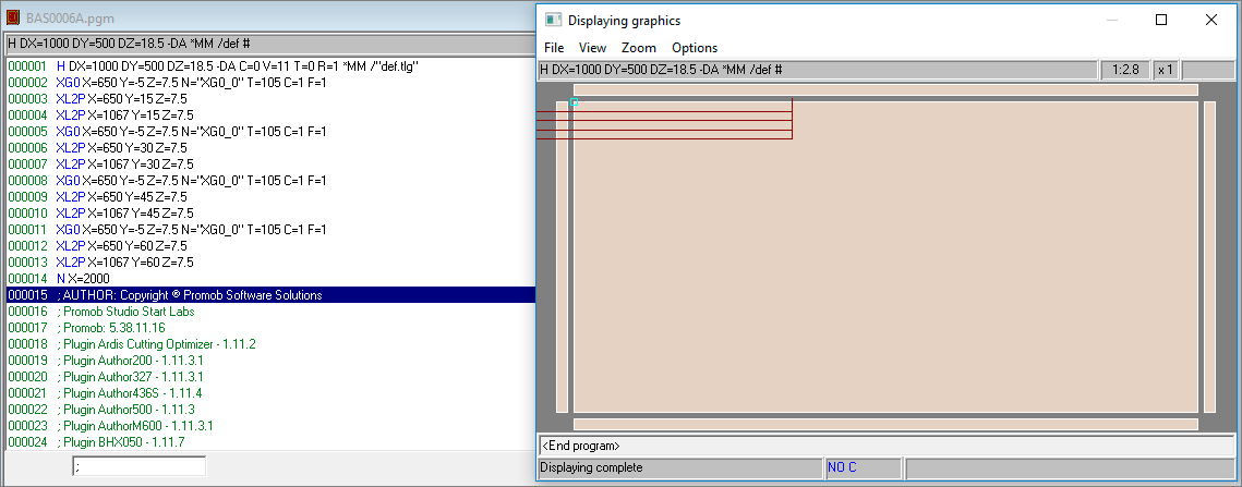
- Angle less than zero:
| Part data | Machining angle | - 45 |
| Part data | Depth | 60 mm |
| Part data | Machining starting point | X= 650, Y = 11 |
| Part data | Machining end point | X = 1030, Y = 11 |
| Part data | Part size | 1000 X 500 X 18,5 mm |
| Tool Data | Cut angle | - 45 |
| Tool Data | Diameter | 5 mm |
| Tool Data | Machining compensation | 1 mm |
| Tool Data | Machining direction | Clockwise |
| Part data | Machining angle | - 45 |
| Part data | Depth | 60 mm |
| Part data | Machining starting point | X= 650, Y = 11 |
| Part data | Machining end point | X = 1030, Y = 11 |
| Part data | Part size | 1000 X 500 X 18,5 mm |
| Tool Data | Cut angle | - 45 |
| Tool Data | Diameter | 5 mm |
| Tool Data | Machining compensation | 1 mm |
| Tool Data | Machining direction | Counter-clockwise |
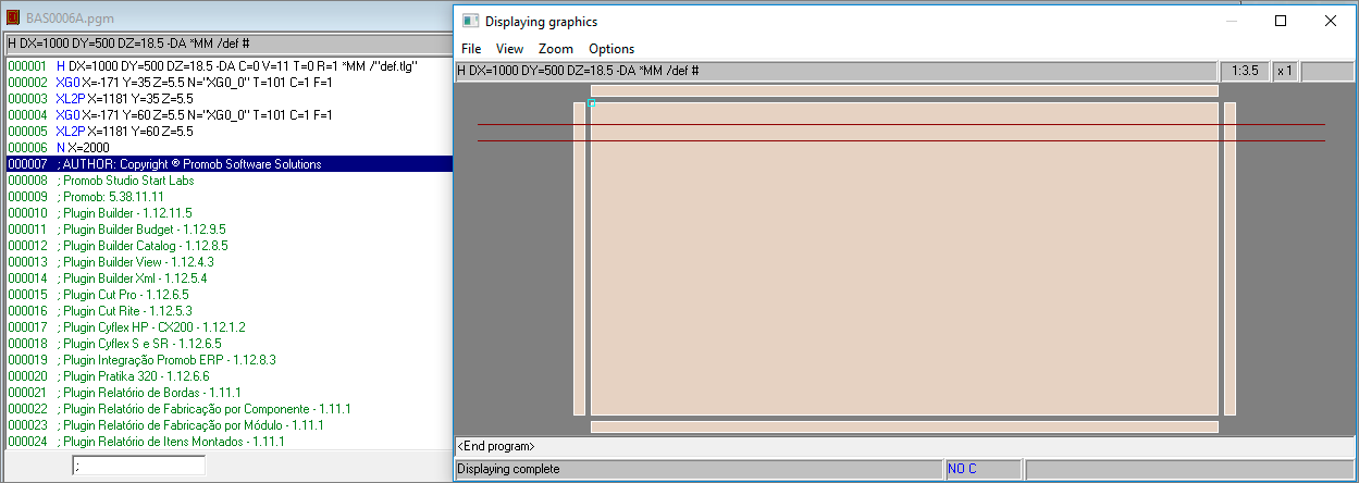
4. Profile machining outside the limits of the part:
- Angle equal to zero:
| Part data | Machining angle | 0 |
| Part data | Depth | 60 mm |
| Part data | Machining starting point | X= - 155, Y = 13 |
| Part data | Machining end point | X = 1165, Y = 13 |
| Part data | Part size | 1000 X 500 X 18,5 mm |
| Tool Data | Diameter | 16 mm |
- Angle greater than zero:
| Part data | Machining angle | 45 |
| Part data | Depth | 60 mm |
| Part data | Machining starting point | X= - 155, Y = 13 |
| Part data | Machining end point | X = 1165, Y = 13 |
| Part data | Part size | 1000 X 500 X 18,5 mm |
| Tool Data | Cut angle | 45 |
| Tool Data | Diameter | 60 mm |
| Tool Data | Machining compensation | 1 mm |

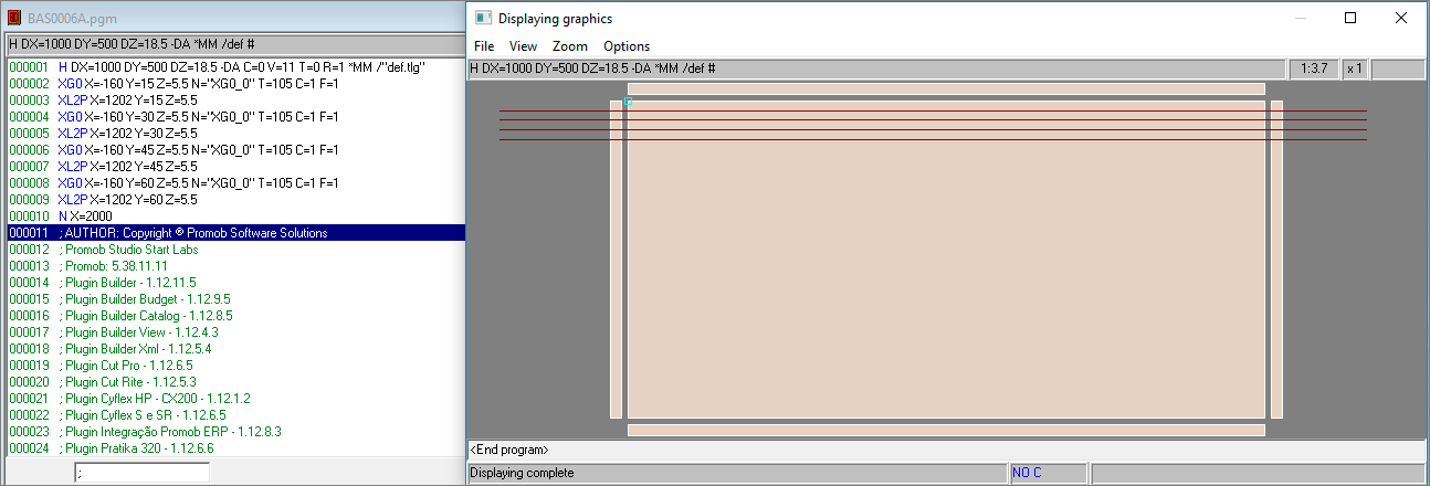
- Angle less than zero:
| Part data | Machining angle | - 45 |
| Part data | Depth | 60 mm |
| Part data | Machining starting point | X= - 155, Y = 13 |
| Part data | Machining end point | X = 1165, Y = 13 |
| Part data | Part size | 1000 X 500 X 18,5 mm |
| Tool Data | Cut angle | - 45 |
| Tool Data | Diameter | 5 mm |
| Tool Data | Machining compensation | 1 mm |
Use of Machining
See below how to use the Plugin Builder machining tools, generate and configure drawings on parts, create technical documentation and programs for machining centers.
The following topics will be covered:
Machining Types
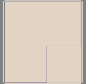
1. Contour machining
It is a machining option where the machine cutter goes around all sides of the part, eliminates imperfections, removes specific scraps, or eliminates overcut measures on the sides of the part.
Example of L machining (for corners):
Contour machining example:
2. Parametric machining
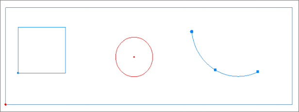
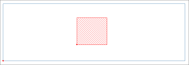
They are toolpaths that can have free forms on the part, such as geometric shapes or lines. They can be contoured or interior only.
Exemplo de usinagens paramétricas de contorno:
Examples of interior parametric machining:
Selection of parametric toolpaths
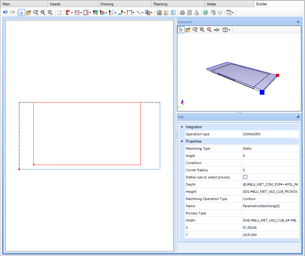
In the module register, on the Builder tab, there is a register with common parametric machining, with ready-made configurations, just place them on the part.

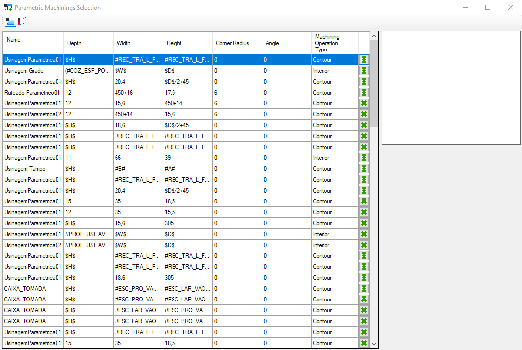
Ao selecionar a primeira opção disponibilizada nas usinagens paramétricas, a mesma possui os valores de Edição conforme a imagem abaixo.
Configure machine plugin and generate programs
In order to generate the machining program for the CNC machine, it is necessary to configure the machine plug-in, select the types of operations that will be performed and which tool will be used.
Below is an example of a machining center configuration for the Pratika 320 - SCM machine:
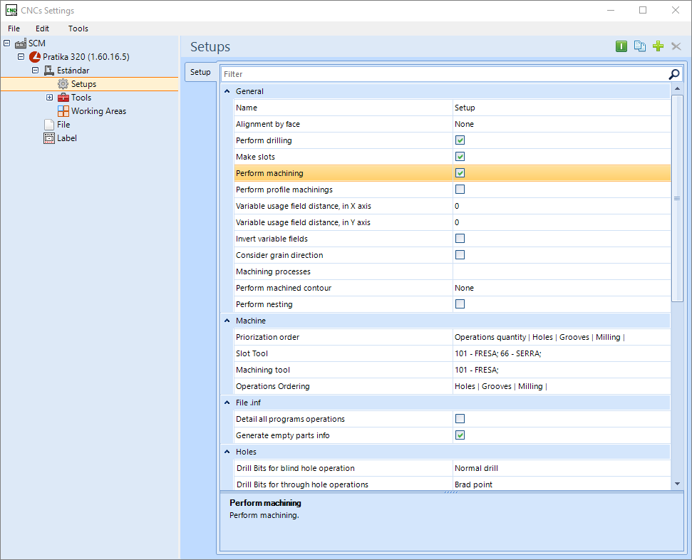
To configure:
1. Check the option Perform machining;
2. Select the options to machine the outline of all parts, only marked parts or none;
3. After that, select the tool to be machined;
- When the plug-in is configured and the machining operations registered, the CNC program can be generated.
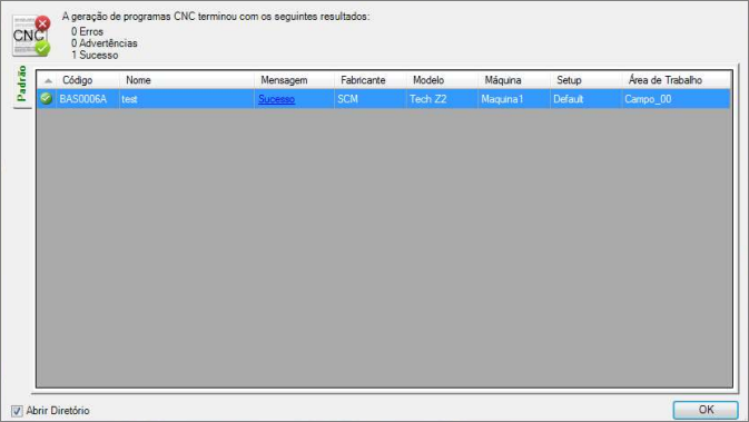
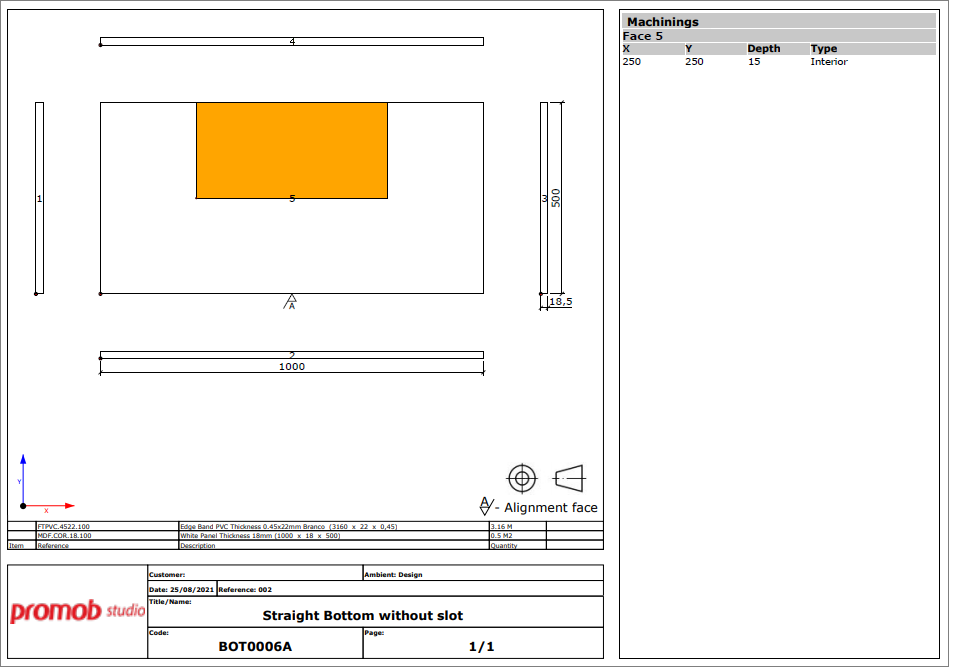
Below, the image of the technical drawing of the part with the machining:
Bridge configuration for through machining
Available from version:
- Plugin Builder – 1.12.12.28 or superior.
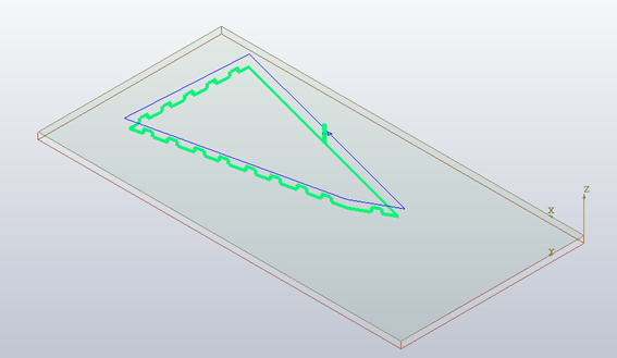
The support bridges in machining ensure that parts of the part that would fall into the machine after the execution of through machining operations remain attached to the part, but in small intervals of smaller thickness, making it easy to manually remove this material later.
When configuring this support, there are three fields to be considered. They can be found in the section Machining with support bridges, in the Machine Setup, where this functionality is available:
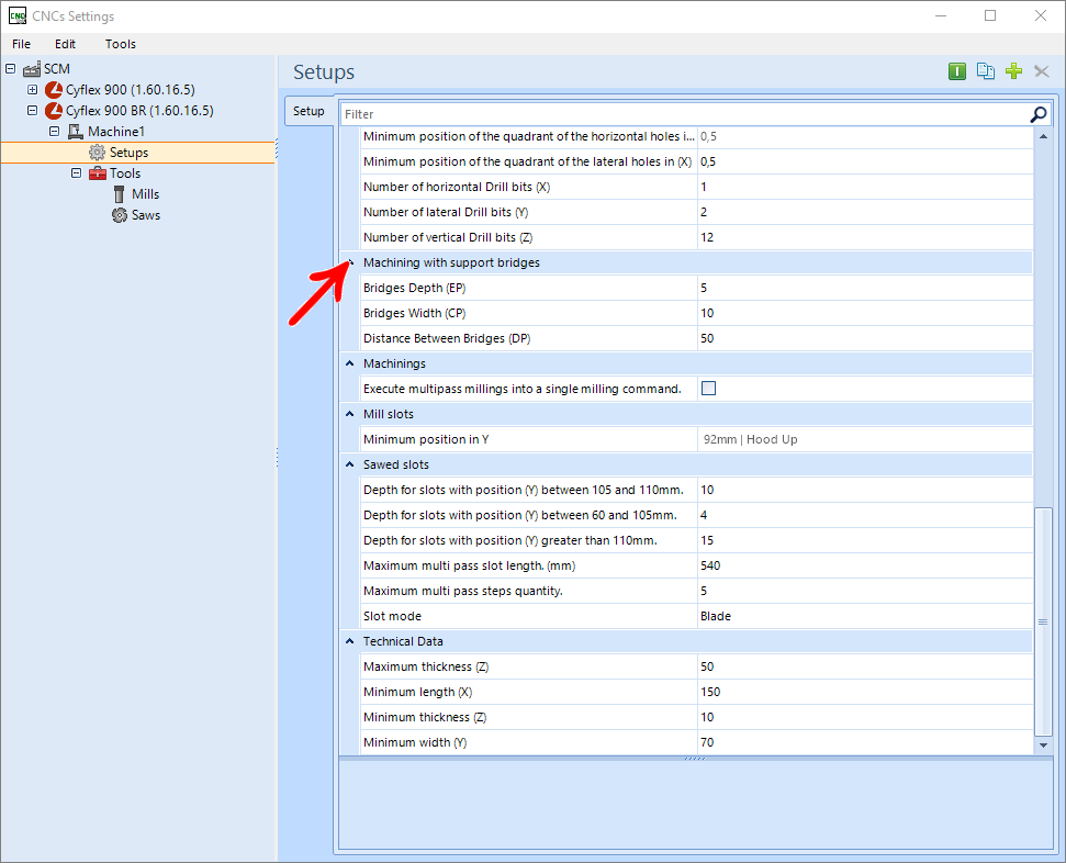
Length of bridges (CP): Defines the length of the intervals where the machining will be performed so that the remaining thickness is equal to that defined in the Thickness of bridges field.
Distance between bridges (DP): Defines the length of the gaps between bridges where the machining will be done, as defined in the registration.
Bridge Thickness (EP): Thickness that will remain in the intervals where support bridges are executed. If this field has a ZERO value, the bridges will not be executed.
IMPORTANT: The bridge will only be executed where the bridge length + tool diameter is smaller than the machined line or arc length.
Program
The construction of bridges can be carried out in two different ways, depending on the machine. The forms are:
1. Machines that have their own command for executing bridges: sends only one machining in the program, with a specific command, informing the machine that that machining must be carried out considering the support bridges. Examples of machines: Cyflex HP, Cyflex 900BR, Cyflex SR.
2. Machines that do not have their own command for executing bridges: sends several machining commands, that is, a command for the tool to go down to the bridge thickness, and then a command for each passing interval between the bridges. Machine example: Evolution 7405.
Eamples:
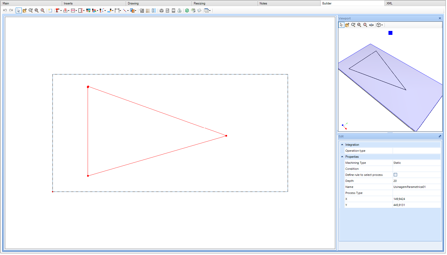
- Bridge setup configuration

- Part registration
- Visualization of the program generated with the bridges
Machining with variant depth
Available from:
- Plugin Builder version 1.12.13.1 and all versions of compatible plugins
Machining with variant depth is only applied for line machining. To register, perform the following procedures:
Machining registration
1. Access the Builder tab in the Modules Editor;
2. Select the desired item;
3. Create a line with two or more points;
4. Apply the desired depth in the machining;
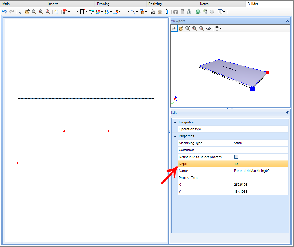
5. At each point it will be possible to apply a different depth.
Example:
• At the starting point, depth (Z) was applied with a value of 5.
• The end point, the depth is set to 0. In this case, the value of the machining depth and not the point value will be used.
In this example the machining has the following values:
• Depth of starting point: 5
• Depth of end point: 10

Machines compatible with this functionality
|
PROFILE MACHINING
|
||
|
BIESSE 1. Rover 1836GFT 2. Rover 2231GFT 3. Rover 24 4. Rover A 1332 5. Rover A 3.30 6. Rover A4 7. Rover B7 8. Rover C9 9. Rover 20 10. Skill 300 K3 11. Skipper V31 12. Skipper 100 13. Skipper 130 |
SCM 1. Pratika 310 2. Pratika 315 3. Pratika 320 4. Pratika 325> 5. Pratika S 6. Tech Z1 7. Tech Z2 8. Tech Z5 9. Tech Z25 10. Tech Z30 |
MORBIDELLI 1. Accord 40 FX 2. Author 200 3. Author 327 4. Author 436S 5. Author 500 6. Author M600 7. M100 8. Unifex 9. Universal NB-3618 10. Universal NB-3622 11. Universal TV-3615 |
|
MACHINING ON THE TOP/BOTTOM FACE
|
|||
|
BIESSE 1. Rover 1836GFT 2. Rover 2231GFT 3. Rover 24 4. Rover A 1332 5. Rover A 3.30 6. Rover A4 7. Rover B7 8. Rover C9 9. Rover 20 10. Skill 300 K3 11. Skipper V31 12. Skipper 100 13. Skipper 130 |
BUSELATTO 1. Jet Optima
GIBEN 1. Flat BDT 2. Flat Selexx 3. Genesis EVO 4. PTP 5. WIBJ-5
MASTERWOOD 1. Project 250 2. Project 450 3. Project TF |
MORBIDELLI 1. Accord 40 FX 2. Author 200 3. Author 327 4. Author 436S 5. Author 500 6. Author M600 7. Cyflex HP 8. Cyflex SR 9. M100 10. Unifex 11. Universal NB-3618 12. Universal NB-3622 13. Universal TV-3615 |
SCM 1. Cyflex 900BR 2. Pratika 310 3. Pratika 315 4. Pratika 320 5. Pratika 325 6. Pratika S 7. Tech Z1 8. Tech Z2 9. Tech Z5 10. Tech Z25 11. Tech Z30 |