Check out this article for information to establish integration with machines from manufacturer Weeke.
If needed, select below on one of the subjects covered in this article:
Homag machine programs using dimension variables
Available from version:
- Plugin Builder 1.11.28 or higher.
When integrating with Homags/Weeke machines, it is possible to position operations using the total dimension of the part through the variables DX and DY in the positions of the operations, where DX indicates part size on the X-axis and DY indicates part size on the Y-axis.
For a given operation to use the functionality, there are three fields in the machine plugin. Variable Usage Field Distance on the X-Axis, Variable Usage Field Distance on the Y-Axis, and Invert Variable Fields. Below the image below the fields added to the plugin:
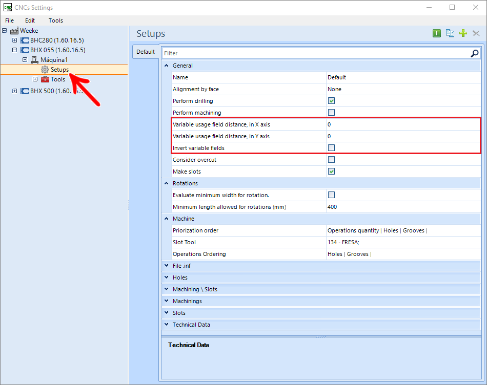
Distance from the variable usage field on the X axis
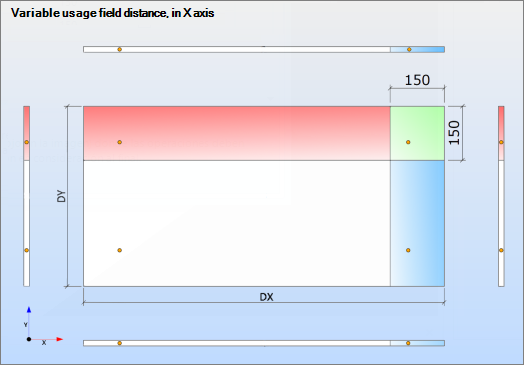
For operations to take DX variable, operations must be within the area determined by the user.
EXAMPLE:

The placed measure refers to the end of the part, so the field where the operation takes the variable, using a 1000 mm long part and the 150 mm field distance as an example, should be above at least 850 mm.
See the illustration below for better understanding, the blue area is the field where operations must meet to take use of variables:
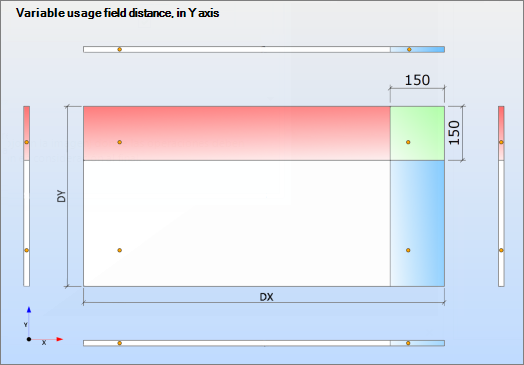
Distance from the field of use of variable on the Y axis
For operations to take variable DY, the operations must be within the area determined by the user.
EXAMPLE:

The measure placed refers to the end of the part, so the field where the operation takes the variable, using a part 500 mm deep and the field distance of 150 mm as an example, should be above at least 350 mm.
Invert variable fields
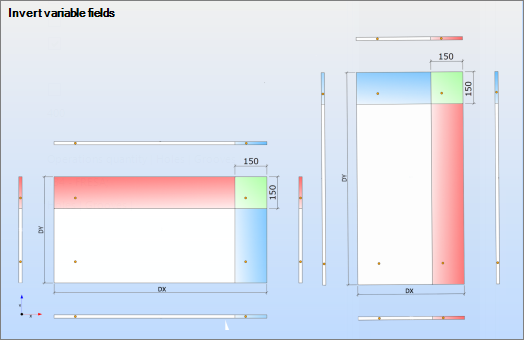
The option Invert variable fields must be checked when the user wants the fields described above to invert when a part is rotated when generating the program. Below is an image of the field in the plugin and an illustration exemplifying field rotation:
EXAMPLE:

Exemplifying field rotation
EXAMPLE:
The program generated, using and not using variable functionality:
- Commands using a variable (Machine program)

- Commands without using a variable (Machine program)

Dynamic Saw Slots on Weeke Machines
Available from version:
- Plugin Builder 1.11.31.1 or higher.
Saws on Weeke machines, registered in the plugin, do not have a defined diameter, therefore, the radius compensation of the saws is not done automatically for through slots on only one side of the part.
As these machines do not perform compensation, the tear will respect the value registered in the displacement, register the tear in the Builder tab, setting the options:
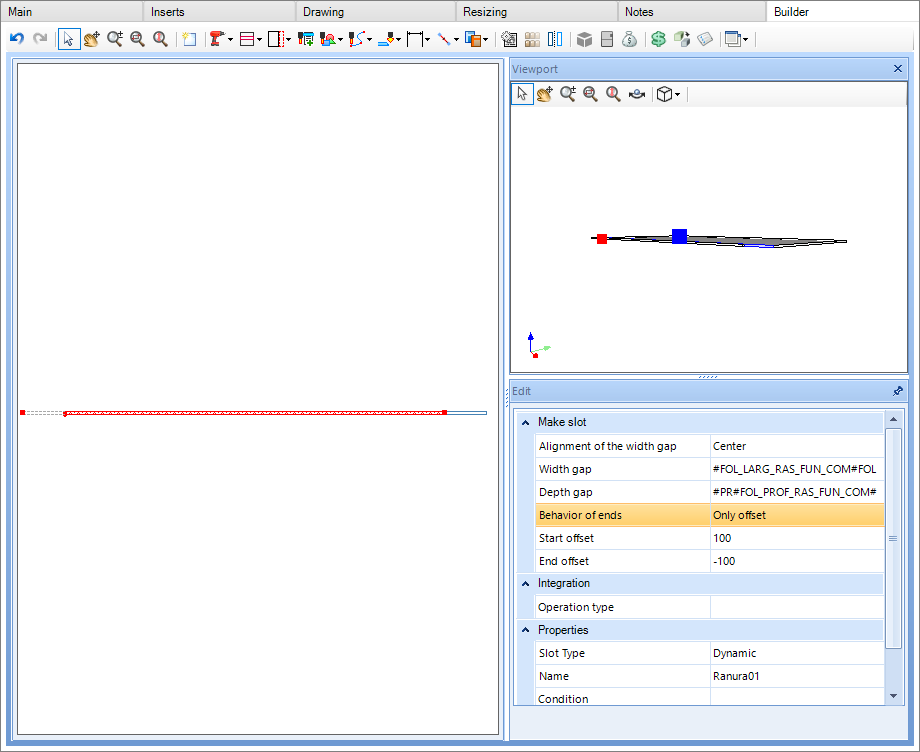
End Behavior: Check Offset only.
Offset from start: It will determine the offset that will be made at the beginning of the tear in relation to the beginning of the part.
- Positive value: shifts the start of the slot towards the outside of the part.
- Negative value: shifts the start of the tear towards the inside of the part.
End Offset: Will determine the offset that will be made at the beginning of the tear in relation to the end of the part.
- Positive value: shifts the end of the slot towards the outside of the part.
- Negative value: shifts the end of the slot towards the inside of the part.
For through slots at both ends, just checking the Through option is sufficient:

EXAMPLE:
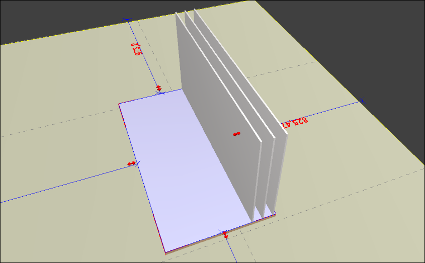
Since we have a Base, and we want to apply three Dynamic rips:
- At Back panel 1 - A tear starting at the end and ending inside the piece
- At Back panel 2 - A tear starting at the inside of the piece and ending at the end
- At Back panel 3 - A tear that goes from one end of the piece to the other.
Back panel 1
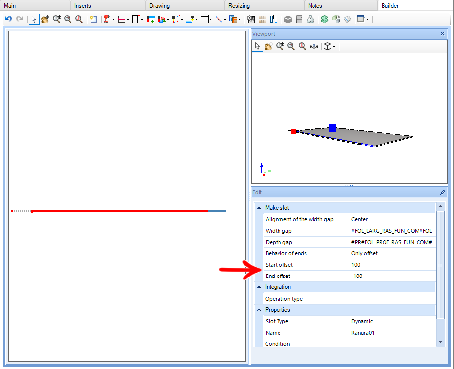
Back panel 2
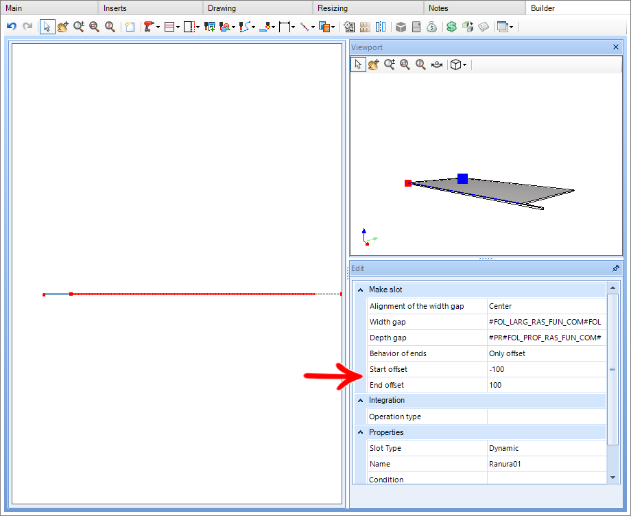
Back panel 3
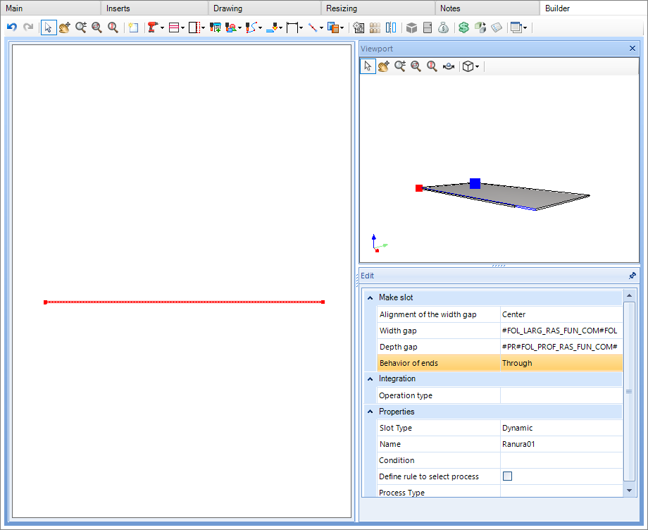
In the 3D space, we insert the funds in the base that will receive the tears:
Then, generating the program, the result will be:
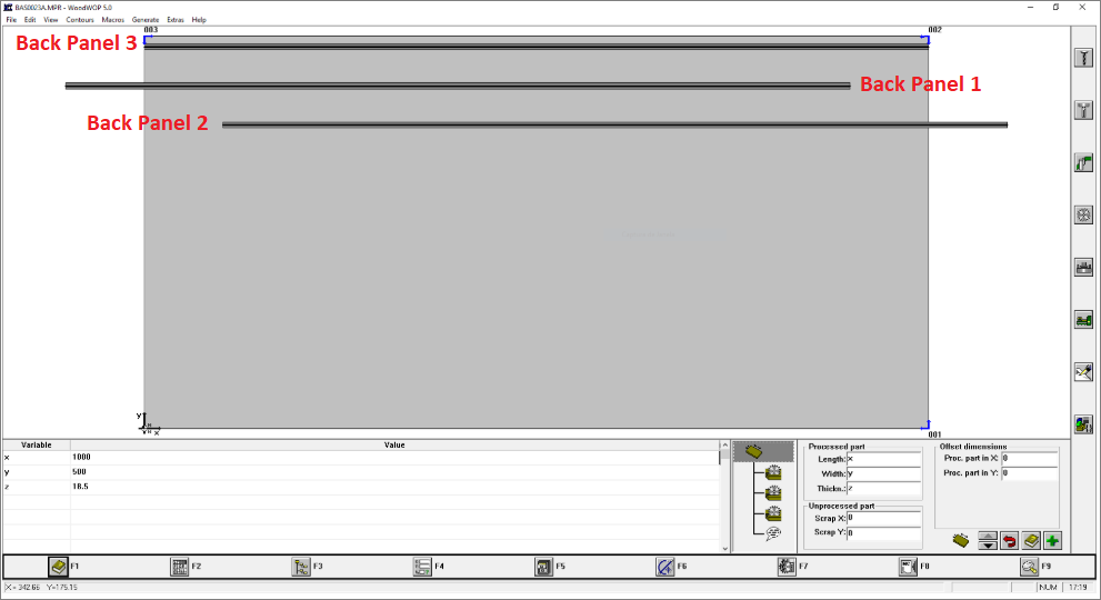
Note that the slots made by back panel 1 and back panel 2 were made with exact respect to the informed displacements.
BHX500 machine head prioritization
The BHX500 machine has two drilling heads, one upper and one lower. By configuring the machine, it is possible to make adjustments regarding the usability of these heads.
Through the option Select, the head(s) select which heads will be used to perform the machine operations.
Choices are Both, Inferior and Superior.
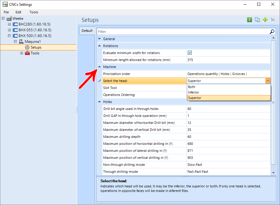
If Both is chosen in this field, it will be possible to indicate which head will be prioritized during the execution of operations.
Select between Inferior and Superior.
EXAMPLE:
In this case, as an example, selecting the Upper head, both heads will be able to perform operations on the parts, but the prioritization will be for the Superior head.
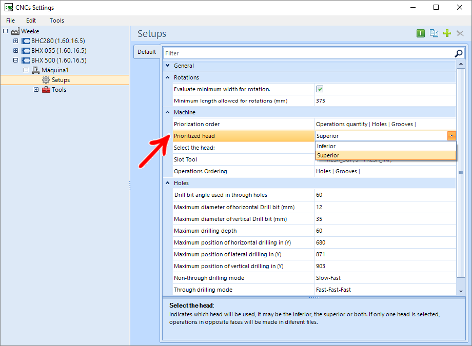
IMPORTANT: Head prioritization will be performed by the face of the part that contains the most features.
Change pattern of holes in Homag machines
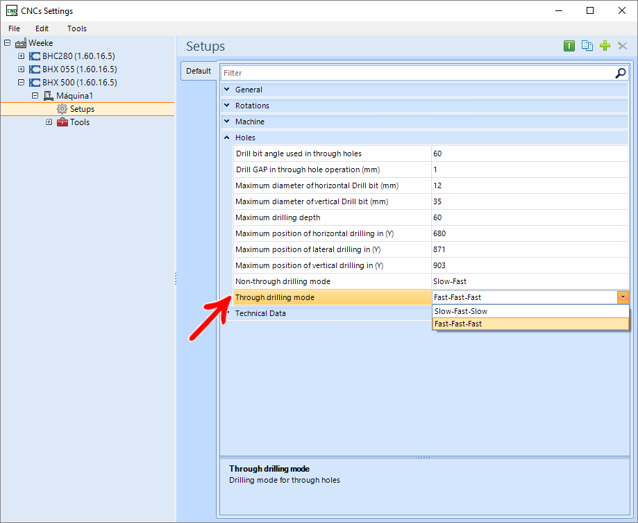
There are in the Setup configurations of Homag machines (BHX and Venture) options that determine the speed of the drills when entering and drilling the part. These options apply to both through and through holes. To change them, we must select the desired options in the plugin:

After generating the programs, we can see the type of hole selected in the MPR file, opening WoodWop and selecting the hole:

Through plunge and milling offset - BHX055
Available from:
- Plugin Builder version 1.60.14.20 or higher
Through plunge and milling offset (mm)
When milling cutters, the Through plunge and milling offset (mm) setting is available.
By default, this property has a value of 0.1, so all machining operations that have a depth that characterizes them as passing through will have an increase in depth of 0.1.

At BHX, this property can receive negative values greater than -10. With a negative value on the property, passing machining will have the set value-added to the machining depth, thus resulting in a smaller depth.
IMPORTANT: The smallest value is restricted to -10, when trying to set a value that is lower than -10, automatically the value is set to -10.
This scenario with negative values is recommended for situations where material falls from the workpiece when machining.
EXAMPLE:
If the machining has a depth of 20 mm (which is equal to the thickness of the part) and the value entered in the Through plunge and milling offset (mm) field is - 2, the final machining depth will be 18 mm.