This article will be addressed the following characteristics of slots registration in the Plugin Builder:
Carefully read the available material and, if you have any questions, contact Catalog Consulting.
Applying dynamic slots
Dynamic slots must always be registered on the profile face (Top) of the geometries, if it is registered on the upper or lower face, the dynamic slot option will not be enabled.
To register a dynamic slot, the following steps must be performed:
1. Within the Promob Catalog, in the chosen geometry register, access the Builder tab and select the desired face through the viewport:
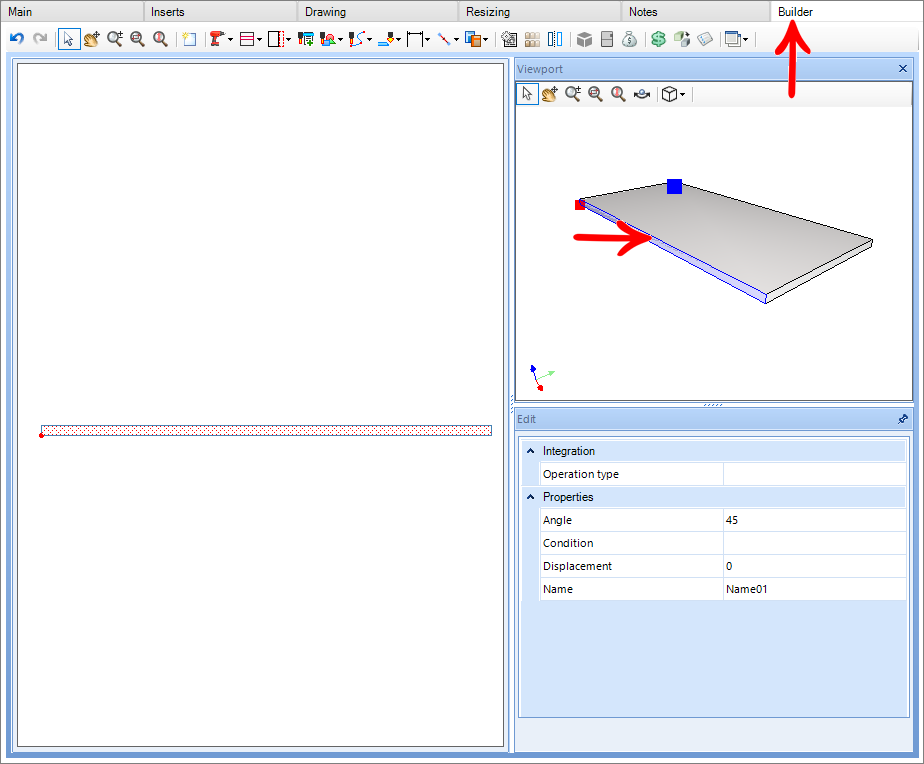
2. After selecting the desired face, click on the Add Slot tool;

3. Select the start point and endpoint of the slot:

NOTES: The starting point will always be the left point, successively the endpoint will be the right point;
4. After applying to the slot, change the slot type option from Static to Dynamic;
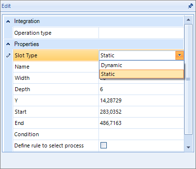
5. Fill in the registration:
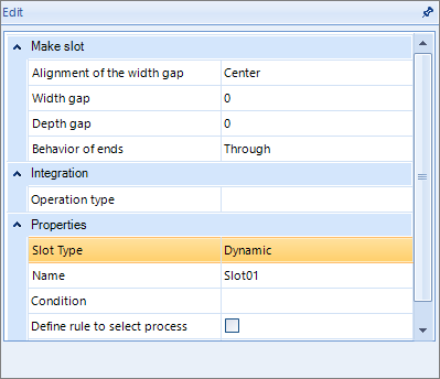

- In case of doubt to fill in, go to Register of dynamic operations.
- After the slot is created, the moment the part comes into contact, the slots will be generated;
- It is important to remember that to generate the slot, the registered part must enter at least 0.1 mm to be ripped.
EXAMPLE:
In the example below, the part made 1 mm contact, then automatically the slot that was generated calculates how much contact the part made and adds it to the gap value in the slot depth.
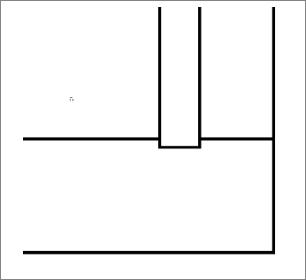
In this case, if the gap registered was 1 mm, the slot generated would have a depth of 2 mm.

Registration of dynamic operations
To configure the Slot Edit measurements, the following procedures must be performed:
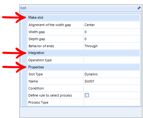
Does slot
Alignment of the width gap: The alignment of this gap has three options:

- Center - aligns the clearance to the center:

- Right - Directs all slack to the Right of the slot:

- Left - Directs all slack to the Left of the slot:

NOTE: The direction that this clearance is applied is influenced by the rotation of the part, that is, if the Right alignment was applied and the part is rotated in the insertion, the clearance will be calculated above the slot and not downwards as in the images above.
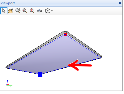
In the gaps shown above, it is important to note that the alignment on the right corresponds to the top of the part, as shown in the image below.
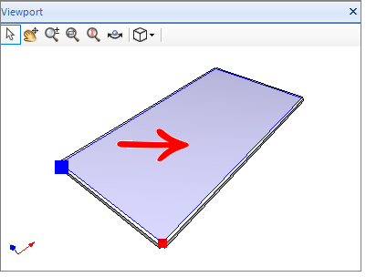
Successively the left alignment corresponds to the bottom of the piece.
Width clearance: Determines the amount of clearance that will be considered;
Depth clearance: Determines how much clearance there will be in the slot depth;
Extremity Behavior: It has four behavior options:
- Through: The slot will always be from one end to the other of the part that will be contacted, regardless of the size of the part that generates the contact;

- Passing Start: Only the beginning of the slot will be passing, for the end of the tear, the value applied in the final displacement of the slot will be respected;

- Passing End: Only the end of the slot will pass, for the beginning of the slot, the value applied in the slot's initial displacement will be respected;

- Only Displacement: It will only respect the initial and final displacement of the slot, which can be passed according to the value entered these fields;

Integration
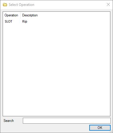
Type of operation: Determines what is the type of operation budget registered for the dynamic tear operation;

Properties
Slot type: Determines whether the slot will be static or dynamic;

Name: Determines what the name of the tear will be;
Condition: Condition that will be applied so that the part generates the dynamic tear, for example, the part will only tear if it has a dimension greater than or equal to 500 mm;
Define rule for process selection: It is possible to define a rule for process selection;
For more information, view Registration and selection of processes – Defining a rule for the selection of processes;
Type of process: It is possible to create and define types of processes for certain machining and/or slot registered in the Builder menu, allowing the use of a certain tool for certain machining and slot, and not in general use for all machining and/or slots;
For more information, view Machining and slot processes;
Registration of top slots operations
On the Builder tab, it is possible to activate top slots to be represented in technical drawings and also perform automation for some specific machines that have an option for this type of operation. They can be dynamic or static.
Settings
1. To create a top slot, create a slot in the top faces of the item;

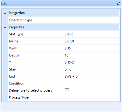
2. Perform the settings normally:
3. Configure the tool in the machine plugin;
- To make these machining operations, use an inclined cutter or saw:

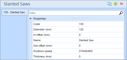
- Inclined saw default configuration:
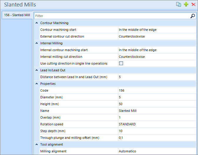
- Standard configuration of the slanted cutter:
4. Enable the operation in the Perform profile grooves checkbox and configure the tool:

NOTE: Top machining operation is available for plug-ins.
- Plugin Venture 1M
- Plugin Venture 2M
- Plugin Venture 3M
- Plugin Venture 8M